Macerating apparatus and method

a technology of a meter and a meter, which is applied in the direction of water installations, grain treatment, constructions, etc., can solve the problems of affecting the service life of the meter, the inability to break into the concrete floor, and the undesirable placement of the toilet on the pedestal, etc., and achieves the effect of convenient maintenance, convenient removal from the meter, and easy movemen

Active Publication Date: 2012-08-16
LIBERTY PUMPS
View PDF5 Cites 27 Cited by
  • Summary
  • Abstract
  • Description
  • Claims
  • Application Information

AI Technical Summary

Benefits of technology

[0012]In accordance with the invention, a macerating apparatus for a toilet is provided in which the problem of unsanitary and / or difficult maintenance of the macerator on a macerating toilet is solved by providing a modular macerating unit that is easily moved to a convenient maintenance position, and if necessary, easily removed from the tank. In certain embodiments, the macerating apparatus may be comprised of a tank having an open top, a macerating unit disposed in the tank, and a main cover joined to the open top of the tank and comprising an opening. The macerating unit is movable from an operating position to a maintenance position beneath the opening. From the maintenance position, the macerating unit may be removed from the tank through the opening in the main cover. The apparatus may be further comprised of an access cover fittable to the opening in the main cover and extending within the tank so as to hold the macerating unit in the operating position when the access cover is fitted to the main cover. The macerating unit may be laterally displaced from the operating position to the maintenance position when the access cover is removed from the main cover. The macerating unit may be disposed in a track on a bottom surface of the tank such that the track guides the motion of the macerating unit between the operating position and the maintenance position.
[0018]The intake basket may be comprised of a cylinder comprising a wall surrounding the cutter, with the inlet tube intersecting the wall of the cylinder. The cutter may be a rotary cutter with the cutting blade defining a plane of rotation, and wherein the asymmetry of the inlet tube is in a lower inward region of the inlet tube and in the plane of rotation of a cutting blade of the cutter. The asymmetry of the inlet tube may be biased toward the lower inward region of the inlet tube in the direction of rotation of the cutter. The increased operating clearance between the cutting blade of the macerating cutter and the intake basket may occur between about 50 and about 100 degrees of cutter rotation. This sector of rotation is biased relative to the inlet tube in the direction of rotation of the cutter, and aligns generally with the lower inward region of the inlet tube.

Problems solved by technology

Breaking into a concrete floor is obviously difficult, and placing a toilet on a pedestal may be undesirable, such as if there is limited overhead clearance.
However, such effluent contains tissue paper and excrement, and may also contain other solid waste such as rags, cigarette butts, sanitary napkins, and even unintended articles such as socks or other objects flushed down by inquisitive children.
The placement of an enclosure with a macerator and a pump at the discharge of a toilet results in certain problems that are not otherwise present with a typical conventional bottom-discharge toilet.
Some of these problems have not been solved by existing macerating toilet systems.
One problem is that because a macerating toilet with a pump and macerator device is more complex than a conventional bottom-discharge toilet, it requires more maintenance.
Cutters on the macerator become worn and dull, and must be periodically replaced.
The macerator system may have level and / or flow sensors which may become fouled and require cleaning or replacement.
In a circumstance where a non-grindable solid object is flushed into the macerator, such as a small toy, it will jam the macerator.
In all cases, because of the sewage present, accessing such components is an unsanitary and unpleasant task.
A second problem is that when certain level and / or flow sensors become fouled, they may provide a false signal such as a high level alarm.
Even though the macerating unit and pump are in working order, the false alarm causes the entire toilet system to become inoperable such that it cannot be used.
The Applicants have observed that when certain solid objects, such as the aforementioned tissue paper, rags, cigarette butts, sanitary napkins, socks, etc., are present within the toilet or within the macerating tank upstream from the macerator and in an unmacerated state, when a flush is initiated, such objects are often drawn into the macerator before it can accelerate to operating speed, and cause the macerator to jam.
Such jamming renders the macerator inoperable.
The Applicants have observed that at the junction between an inlet tube and a macerating basket of a macerator, if a tight running clearance between a cutter blade tip and the basket or inlet tube is maintained, a relatively high frequency of jamming of solid objects between the macerator blade and the basket of inlet tube occurs.
Such jamming renders the macerator inoperable.

Method used


Image

  • Macerating apparatus and method
  • Macerating apparatus and method
  • Macerating apparatus and method

Examples


Embodiment Construction

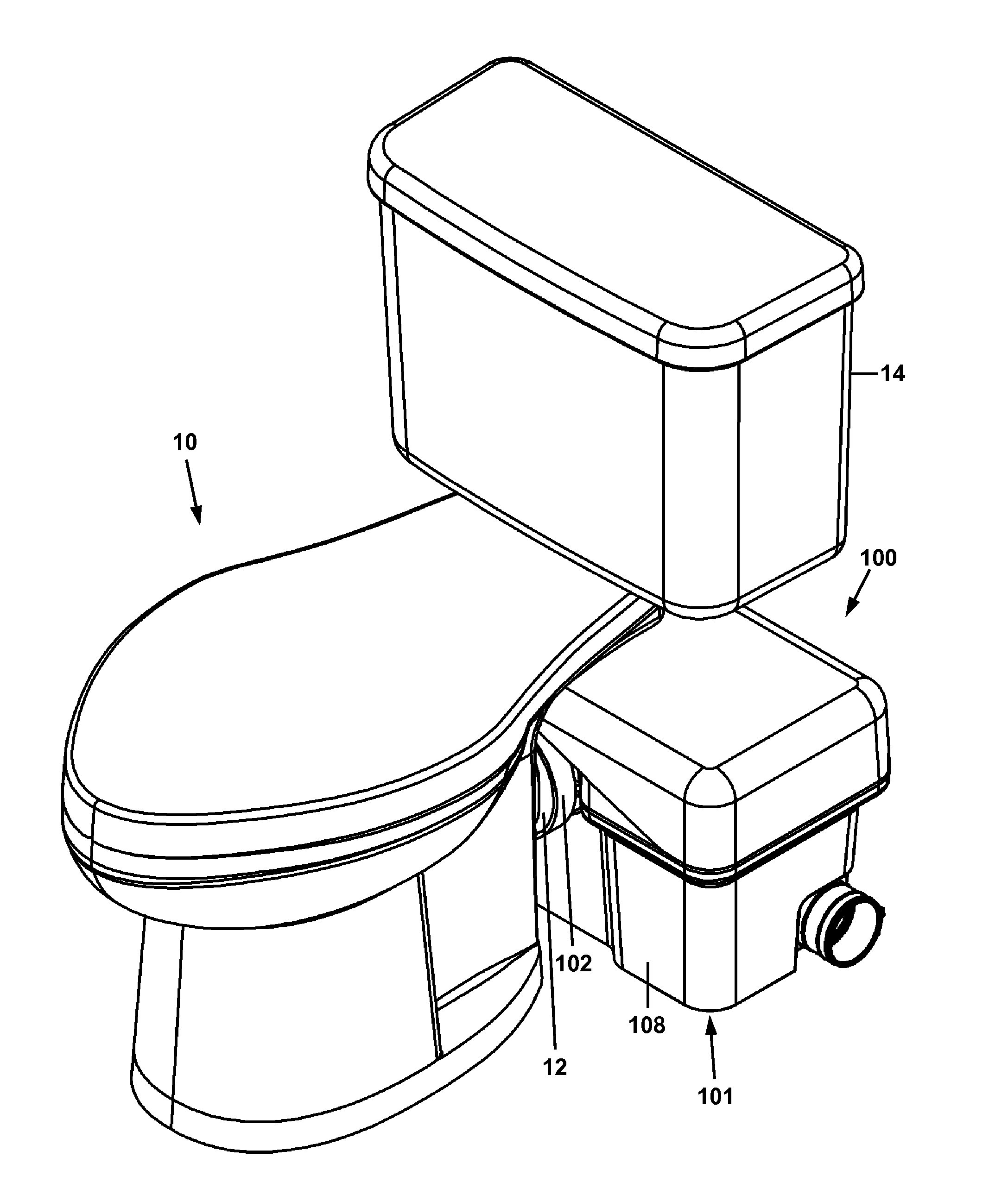
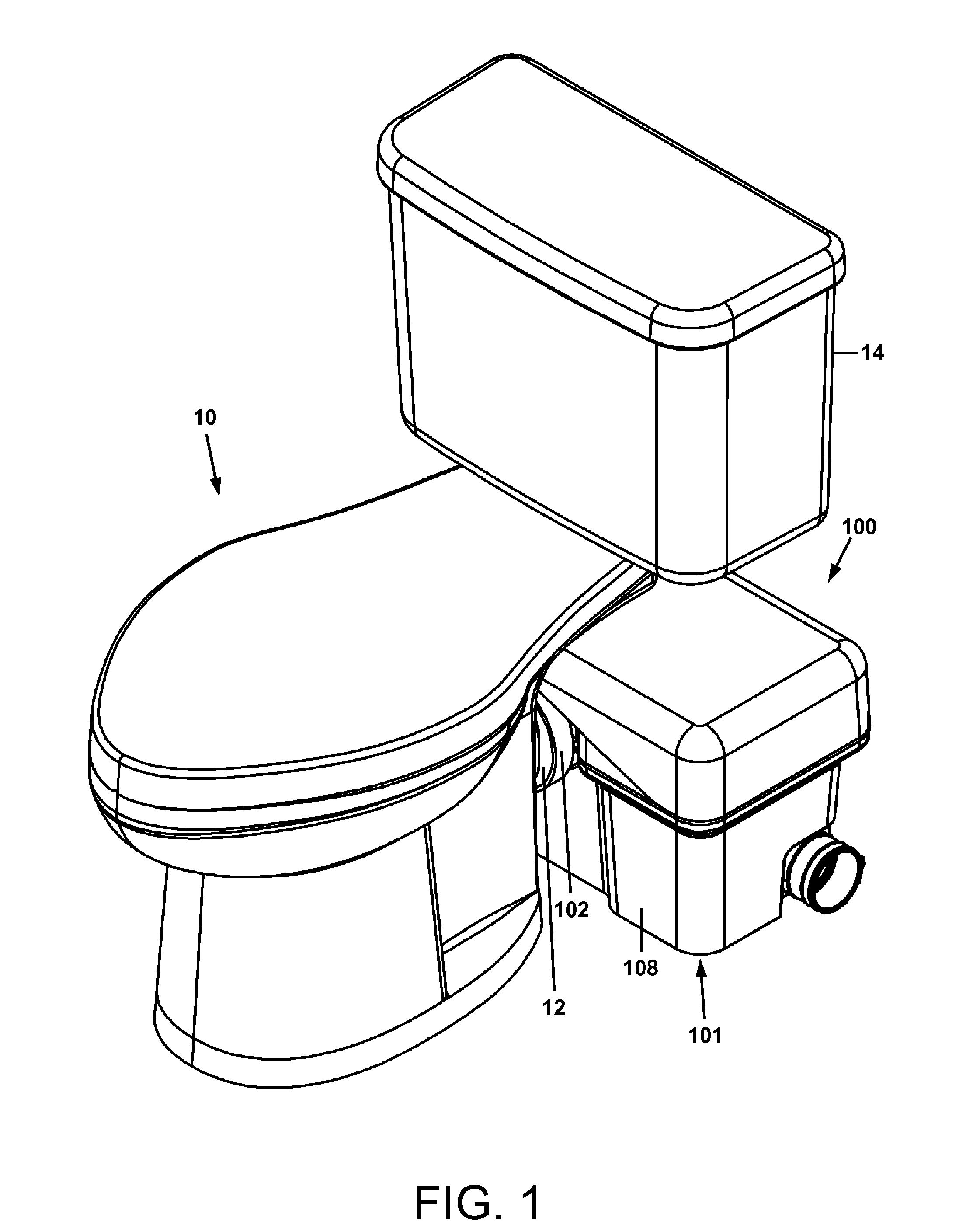
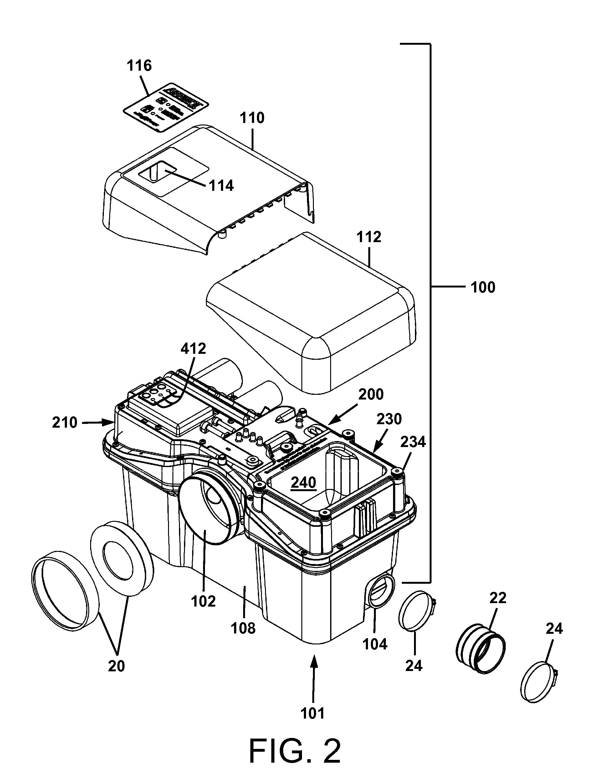
[0040]For a general understanding of the present invention, reference is made to the drawings. In the drawings, like reference numerals have been used throughout to designate identical elements. In the following disclosure, the present invention is described in the context of its use as a macerating apparatus for a toilet. However, it is not to be construed as being limited only to use in macerating the solids that may be present in an effluent stream from a toilet. The invention is adaptable to any use in which macerating of solids in a liquid stream is desirable to be provided from a macerating apparatus. Additionally, the description identifies certain components with the adjectives “front,”“rear,”“top,”“upper,”“bottom,”“lower,”“left,”“right,” etc. These adjectives are provided in the context of use of the macerating apparatus as connected to a toilet and in the context of the orientation of the drawings. The description is not to be construed as limiting the macerating apparatus...


PUM

PropertyMeasurementUnit
rotationaaaaaaaaaa
voltageaaaaaaaaaa
length of timeaaaaaaaaaa

Abstract

A macerating apparatus for a toilet in which the problem of jamming the macerator at startup is solved by rapidly detecting the flushing of the toilet and accelerating the macerator before motion-jamming solid objects in the effluent from the toilet can reach the macerator. The macerating apparatus may be comprised of a macerating cutter operatively connected to a motor, and a sensor in communication with the motor. The sensor may detect the flow of effluent from the toilet toward the macerator, the flow of makeup water from the supply tank into the toilet, or the mechanical action of the mechanism used to flush the toilet. The apparatus may include an intake basket having an asymmetric inlet tube and containing the macerating cutter, wherein the asymmetry of the inlet tube provides additional operating clearance between a cutting blade of the macerating cutter and the intake basket.

Description

BACKGROUND[0001]1. Field of the Invention[0002]Macerating toilet systems, which may be operated at a location below gravity drain piping, and which may also be installed without requiring connection to a drain pipe that is located below the surface upon which such a system is disposed.[0003]2. Description of Related Art[0004]Maceration, in sewage treatment, is the use of a machine that reduces solids to small pieces in order to deal with tissue paper, excrement, rags and other solid waste. Macerating toilets use a grinding or blending mechanism to reduce human waste to a slurry, which can then be moved by pumping. Such a toilet is useful in situations where the desired location of the toilet is below the location of gravity drain piping in a building, thus requiring the effluent from the toilet to be pumped upwardly to reach the discharge location of sewage piping from the building. Such a toilet is also useful because it may be configured so as to discharge laterally from its base,...

Claims


Application Information

Patent Timeline
Patent Type & Authority Applications(United States)
IPC IPC(8): E03D9/10
CPCB02C18/0092Y10T29/49721E03D11/11E03D9/10
Inventor POHLER, DONALD M.HEINSLER, MATTHEW S.
Owner LIBERTY PUMPS
Why Eureka
Try Eureka