
Lift apparatus for a watercraft

a technology for lifting apparatuses and watercraft, which is applied in the field of watercraft lifting assemblies, can solve the problems of long time-consuming and labor-intensive problems of large-sized boats, difficult implementation of solutions, and large modification of boats

Inactive Publication Date: 2010-06-15
A&B MACHINING
View PDF4 Cites 6 Cited by
  • Summary
  • Abstract
  • Description
  • Claims
  • Application Information

AI Technical Summary

Benefits of technology

The apparatus allows for safe and efficient deployment and stowage of watercraft without obstructing the swim platform, reducing the risk of injury and loss of components, while maintaining full use of the platform when not in use.

Problems solved by technology

The storage and deployment of small watercraft from larger boats has long been problematic.
Certain of these solutions are quite difficult to implement and require extensive modification to the boat.
For casual leisure boat users, such modifications are quite expensive, as are the devices themselves.
Often, these components cause injury to users of the swim platform.
In some instances, the components are removable, however, in such cases, many get lost or inadvertently fall overboard and sink.

Method used


Image

  • Lift apparatus for a watercraft
  • Lift apparatus for a watercraft
  • Lift apparatus for a watercraft

Examples


Embodiment Construction

[0029]While this invention is susceptible of embodiment in many different forms, there is shown in the drawings and described herein in detail a specific embodiment with the understanding that the present disclosure is to be considered as an exemplification and is not intended to be limited to the embodiment illustrated.

[0030]It will be understood that like or analogous elements and / or components, referred to herein, may be identified throughout the drawings by like reference characters. In addition, it will be understood that the drawings are merely schematic representations of the invention, and some of the components may have been distorted from actual scale for purposes of pictorial clarity.

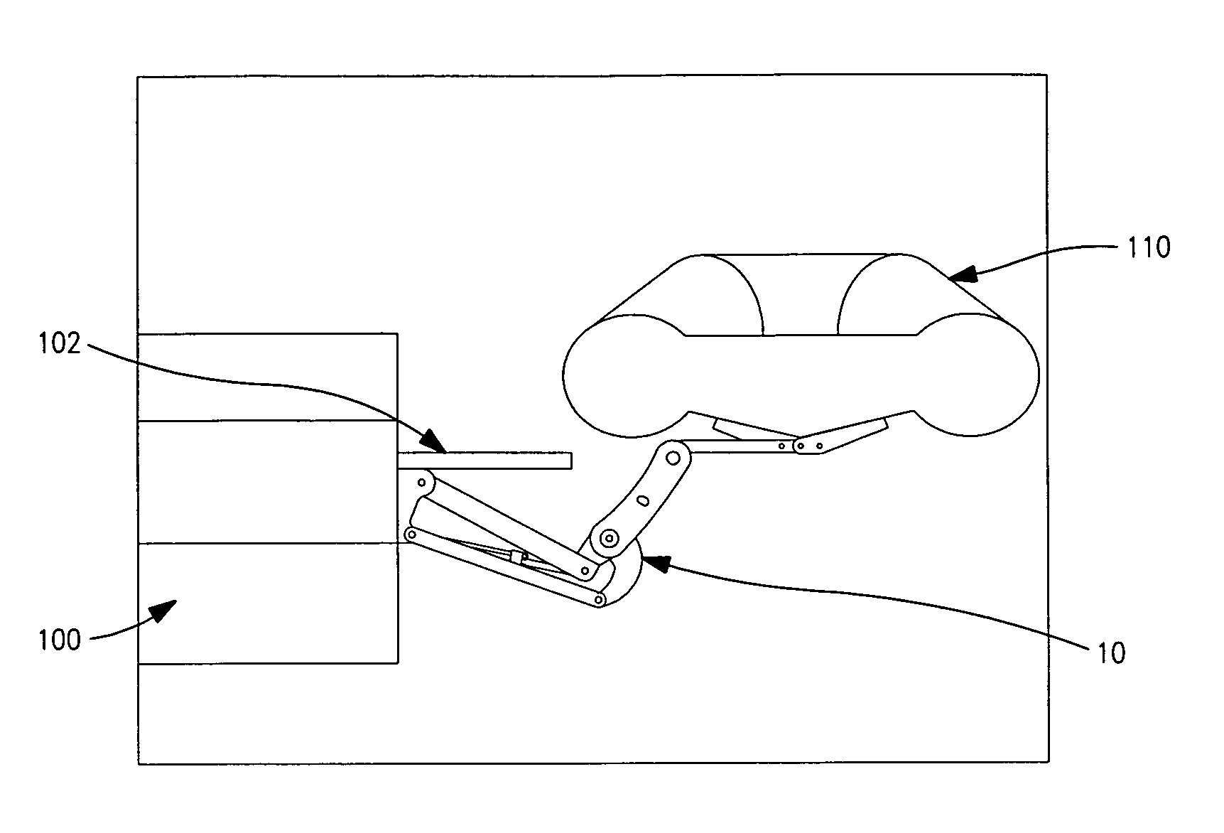
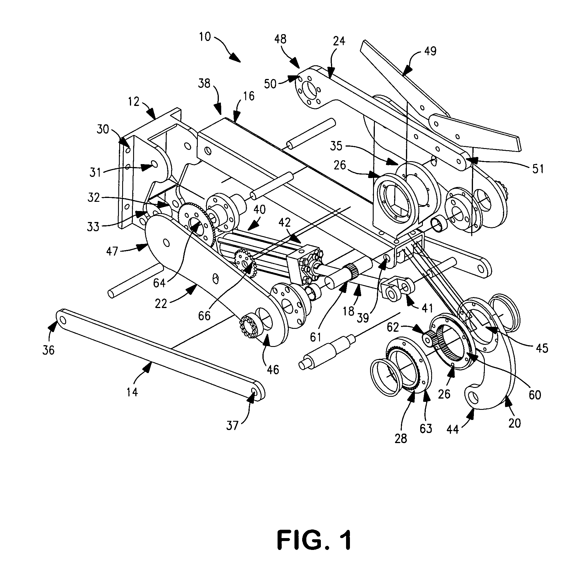
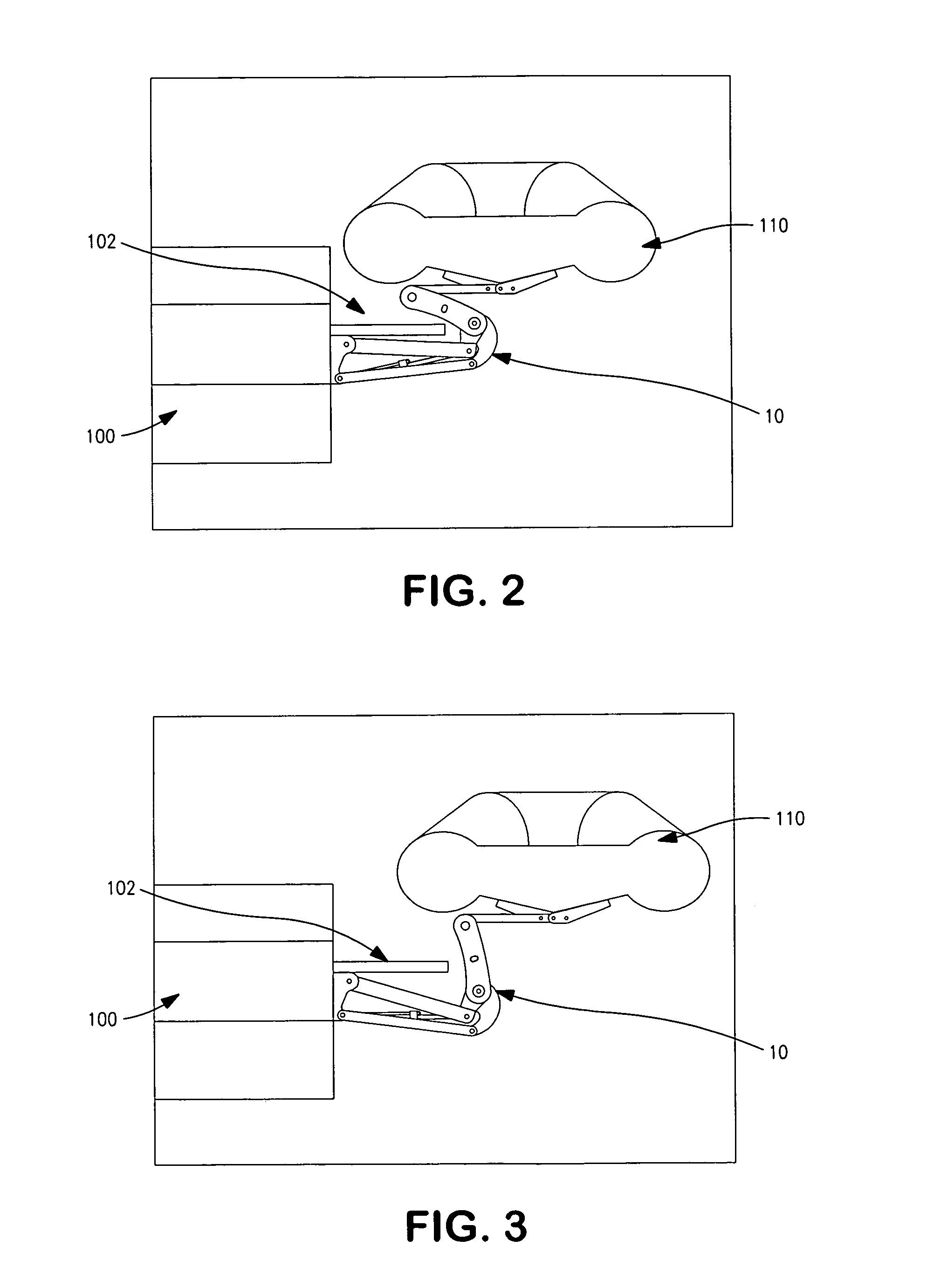
[0031]Referring now to the drawings and in particular to FIG. 1, lift apparatus is shown generally at 10. The lift apparatus 10 is configured to selectively deploy and undeploy (or stow) a watercraft 110 from a platform 102 of a boat 100. Initially, in an undeployed orientation, the watercraf...


PUM


Abstract

A lift apparatus for a watercraft having a plurality of components positioned below the platform at the aft end of a boat. The lift apparatus is configured to lift and deploy a watercraft from an undeployed orientation overlaying a platform to a deployed orientation away from the platform and on the water. In the deployed orientation the platform is substantially free from any lift apparatus component interference.

Description

BACKGROUND OF THE DISCLOSURE[0001]1. Field of the Disclosure[0002]The disclosure relates in general to watercraft lifting assemblies, and more particularly, to a lift apparatus for a watercraft. Although not limited thereto, the lift apparatus is particularly useful for the deployment of watercraft that are typically positioned on a platform (such as a swim platform) of a boat.[0003]2. Background Art[0004]The storage and deployment of small watercraft from larger boats has long been problematic. For many leisure boats, a watercraft, such as a dingy, is often carried behind the boat, and, often on the swim platform.[0005]With some dingys being quite large, there have been developed a number of mechanisms that can assist with the placement of the dingy on a fabricated extension of the swim platform. Certain of these solutions are quite difficult to implement and require extensive modification to the boat. For casual leisure boat users, such modifications are quite expensive, as are th...

Claims


Application Information

Patent Timeline
Patent Type & Authority Patents(United States)
IPC IPC(8): B63B35/40
CPCB63B23/32B63B27/16B63B27/36
Inventor BORUM, PAUL W.DOANE, ROGER
Owner A&B MACHINING
Learn More