Hybrid lighting system

a hybrid lighting and solar energy technology, applied in lighting applications, instruments, using daylight, etc., can solve the problems of high variance in light that is directed into the building interior, the intensity of sunlight entering through the skylighting system may be, at times, too much, and no skylight system can completely compensate for the variance in sunligh

Active Publication Date: 2010-06-15
ABL IP HLDG
View PDF29 Cites 62 Cited by
  • Summary
  • Abstract
  • Description
  • Claims
  • Application Information

AI Technical Summary

Problems solved by technology

The problem with many such skylighting systems is the highly variable amount of light that is directed into the building interior, due to the variance in the intensity of ambient sunlight from season to season, day to day, and even hour to hour.
Further, depending on the climate and season, the intensity of sunlight entering through the skylighting system may be, at times, too much, either in terms of the brightness of the light, or in the heating of the building interior.
No skylight system can completely compensate for the variance in sunlight over the course of a day, from dawn to dusk.
The problem with this system is that the artificial lighting apparatus shades or blocks the sunlight from entering the building.
The problem remains, then, to provide a lighting system that can seamlessly and efficiently control the intensity of light directed into interior of a building from a skylighting apparatus.
None of the prior approaches has been able to provide a simple skylighting system that is adapted to convey a steady source of light year round to a building interior.

Method used


Image

  • Hybrid lighting system
  • Hybrid lighting system
  • Hybrid lighting system

Examples


Embodiment Construction

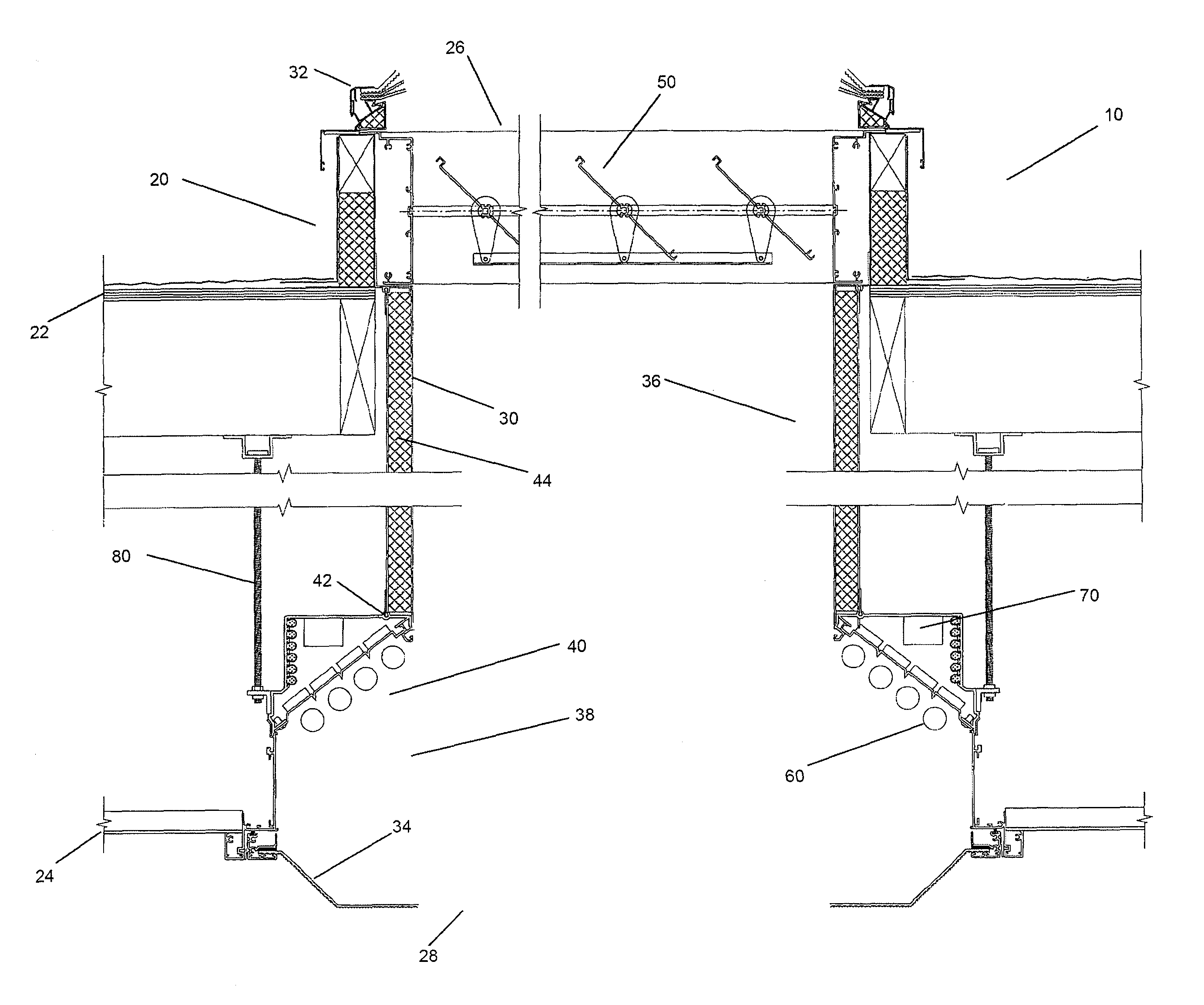
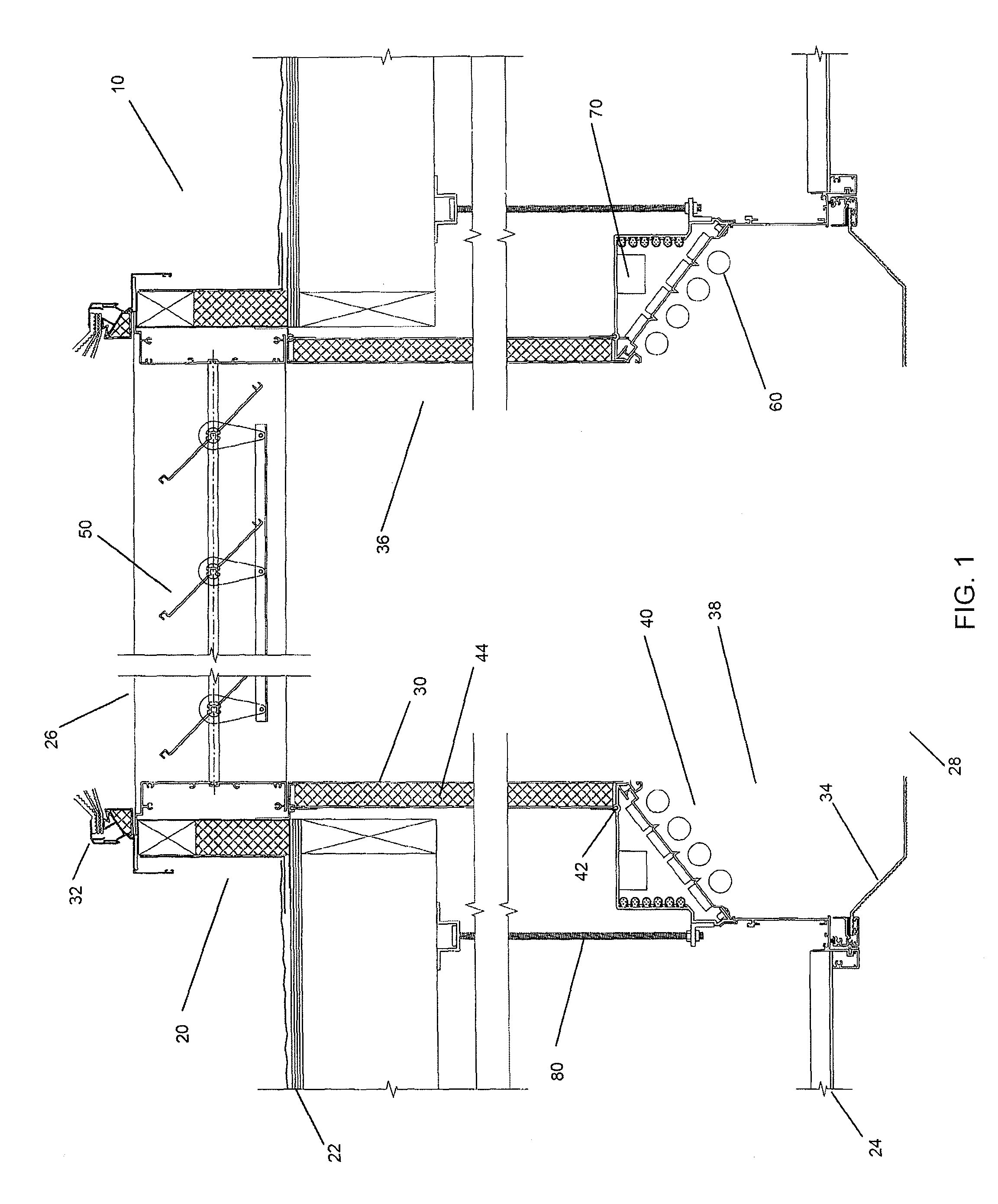
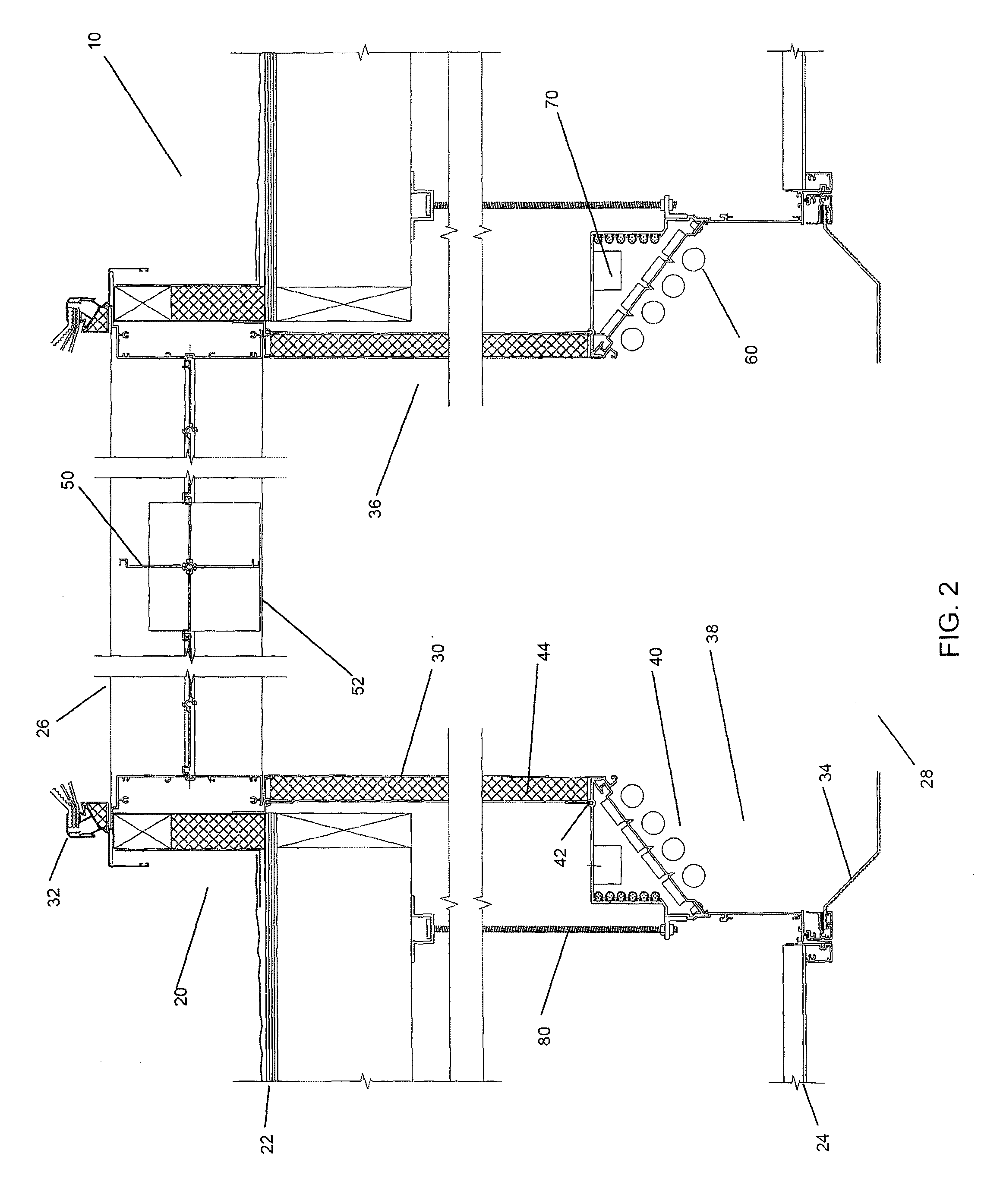
[0033]This invention provides a single fixture, integrated passive solar and electric lighting apparatus, or system 10, which can include digital controls to provide optimal user control while maximizing energy savings.

[0034]In reference now to FIGS. 1, 2 and 3, the passive solar lighting and electric lighting system, or lighting apparatus 10 generally comprises a tubular defined by a frame 20 spanning the roof 22 and interior ceiling 24 of a building, the frame 20 having a first opening 26 at the building roof 22 and a second opening 28 opposed to the first opening 26, and located generally at the level of the building ceiling 24.

[0035]A reflective lining 30 for the frame 20 is located between the first opening 26 and second opening 28. The highly reflective, insulated light well liner 30 is attached to the frame by conventional means, and can be extended any distance as required to span the roof 22 to ceiling 24 distance.

[0036]A skylight 32 covers the first opening 26 and a prisma...


PUM


Abstract

The invention provides a lighting apparatus comprising: a) a frame spanning the roof and interior of a building, the frame having a first opening at the building roof and a second opening opposed to the first opening at the building ceiling; b) a skylight at the first opening; c) a reflective lining between the first and second openings; d) a light diffuser at the second opening; and e) at least one artificial light source located between the skylight and the diffuser; where the artificial light source is positioned at the frame periphery.

Description

REFERENCE TO RELATED APPLICATIONS[0001]This application claims the benefit of U.S. Provisional Patent Application No. 60 / 944,733, filed Jun. 18, 2007, the complete disclosure of which is incorporated herein, in its entirety.COPYRIGHT NOTICE[0002]A portion of the disclosure of this patent document contains material that is subject to copyright protection. The copyright owner has no objection to the facsimile reproduction by anyone of the patent document or the patent disclosure, as it appears in the Patent and Trademark Office patent files and records, but otherwise reserves all other copyright rights.BACKGROUND OF THE INVENTION[0003]1. Field of the Invention[0004]The present invention relates passive solar and electric lighting systems.[0005]2. Description of Related Art[0006]Various roof lighting, or skylighting, systems have been developed for directing sunlight through the roof to the building interior.[0007]U.S. Pat. No. 6,604,329, describes a common skylighting system, for thos...

Claims


Application Information

Patent Timeline
Patent Type & Authority Patents(United States)
IPC IPC(8): F21S8/00
CPCE04D13/033F21S19/005F21V11/04E04D2013/0345F21S11/00F21V23/0442F21V11/00
Inventor BLOMBERG, JEROME O.
Owner ABL IP HLDG
Why Eureka
Try Eureka