Control of white-etched layer during machining

a technology of machining and control, which is applied in the direction of manufacturing tools, other manufacturing equipment/tools, forging/pressing/hammering apparatus, etc., can solve the problems of high cost of broach tools, limited tool life, uneven surface, etc., and achieve the effect of improving the scrap rate of parts due to the integrity of the defected surface integrity

Active Publication Date: 2010-06-15
RAYTHEON TECH CORP
View PDF37 Cites 6 Cited by
  • Summary
  • Abstract
  • Description
  • Claims
  • Application Information

AI Technical Summary

Benefits of technology

[0009]A machining system is disclosed that includes a support configured to retain an article, such as a rotor disk, having an area, such as a surface of a slot in the disk. A cutting tool, for example, a broach, is movable relative to the support to cut the area. A heating member, such as a laser, is con

Problems solved by technology

Broaching nickel-based super-alloys may induce undesired surface characteristics such as excessive material strain hardening and surface microstructure alteration, which typically results in an uneven surface due to deflection during machining.
Aside from the high cost of the broach tools and limited tool life, part scrap rate will increase due to the defected surface integrity.
Although heating and rapid cooling increases surface hardness, this process also induces an internally stressed microstructure that makes the surface brittle.
Although tempering facilitates avoidance

Method used


Image

  • Control of white-etched layer during machining
  • Control of white-etched layer during machining

Examples


Embodiment Construction

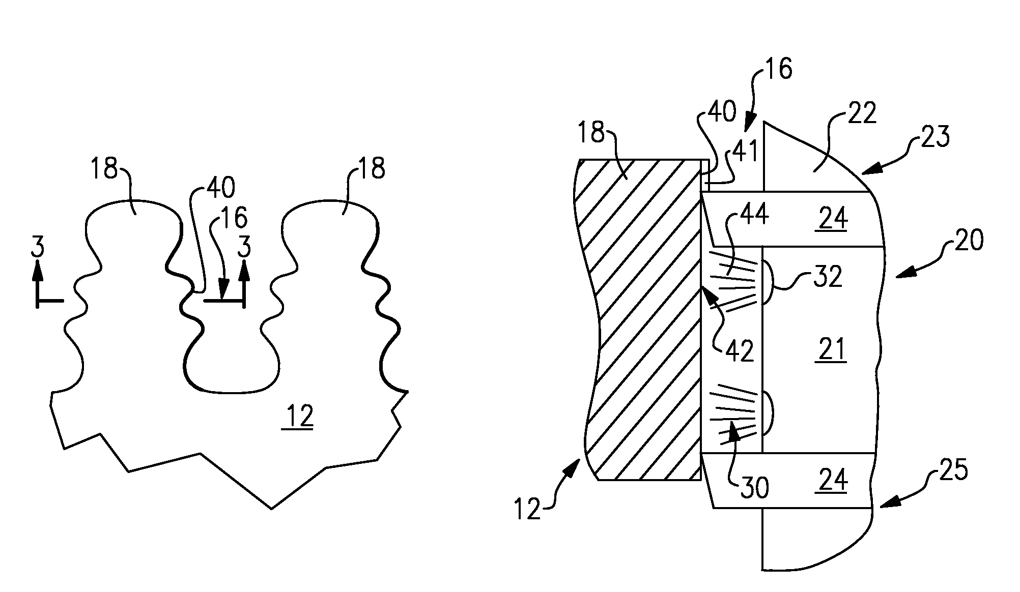
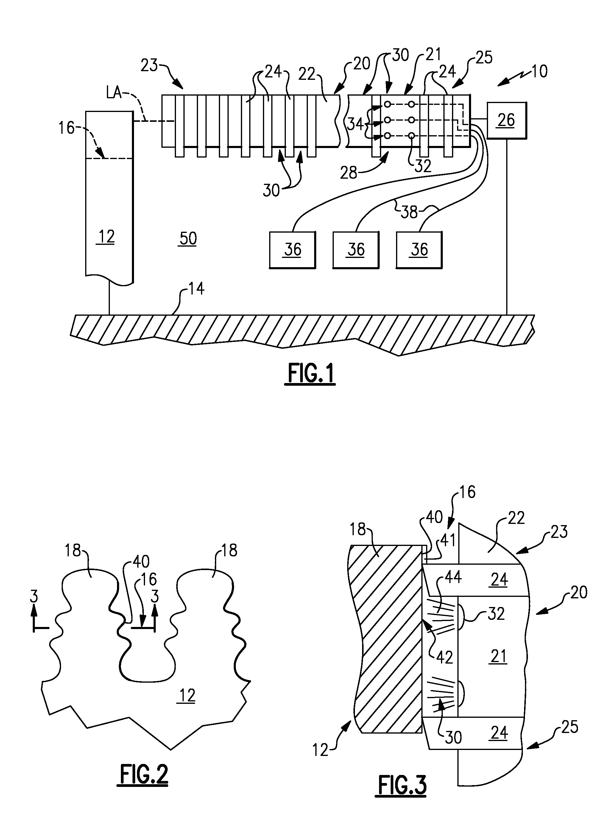
[0015]A machining system 10 is generally depicted in FIG. 1. The system 10 includes a support 14 that retains an article 12, such as a rotor disk. An example rotor disk is shown in more detail in FIG. 2. The rotor disk includes a slot 16 provided between lugs 18. The slot 16 is complementarily shaped to receive a fir-tree root of a rotor blade. Other slot shapes may be used to secure rotor blades to the rotor disk.

[0016]Returning to FIG. 1, a cutting tool 20 is movable relative to the article 12 to cut an area 42 of the article 12, best shown in FIG. 3. In one example, the cutting tool 20 is a broach tool. For example, a broach tool includes a body 22 supporting multiple teeth 24 that are spaced from one another from a forward end 23 to a rearward end 25 to provide gaps 30 between the teeth 24, as shown in FIGS. 1 and 3. The teeth 24 extend along a longitudinal axis LA of the body 22. The forward end 23 typically includes teeth that more aggressively cut the slot 16 than the teeth o...


PUM

PropertyMeasurementUnit
Depthaaaaaaaaaa
Areaaaaaaaaaaa
Thermal conductivityaaaaaaaaaa

Abstract

A machining system includes a support configured to retain an article, such as a rotor disk, having an area, such as a surface of a slot in the disk. A cutting tool, for example, a broach, is movable relative to the support to cut the area. A heating member, such as a laser, is configured to locally heat the area of the article. In one example, the cutting tool includes a body having a cutting edge. The heating member is supported by the body and is configured to provide heat adjacent to the cutting edge. The cutting edge cuts the locally heated area while the area is still heated.

Description

BACKGROUND[0001]This disclosure relates to a cutting tool and a method of machining.[0002]A rotor of a typical gas turbine can have more than one hundred blades that are secured to rotating disks. The blade / disk attachment scheme includes providing a root on each blade that is secured to the disk. One type of root used to attach blades, commonly referred to as a “fir tree,” includes a convoluted section that has a complementarily shaped slot in the disk periphery.[0003]Broaching is one common method used to manufacture fir tree slots. Broaching nickel-based super-alloys may induce undesired surface characteristics such as excessive material strain hardening and surface microstructure alteration, which typically results in an uneven surface due to deflection during machining. A white-etched layer (WEL) on the surface is one indication of undesired surface characteristics. Aside from the high cost of the broach tools and limited tool life, part scrap rate will increase due to the defe...

Claims


Application Information

Patent Timeline
IPC IPC(8): B23D37/22B23P23/00
CPCB23D37/22B23D43/04B23P25/006B23D2043/025Y10T409/405775Y10T29/5147Y10T29/49316Y10T407/16Y10T409/400175Y10T29/49995Y10T29/5176Y10T409/40105Y10T29/49321Y10T83/0414Y10T83/293Y10T83/283
Inventor EL-WARDANY, TAHANY IBRAHIMBURLATSKY, SERGEI F.GUO, CHANGSHENGSCHMIDT, WAYDE R.
Owner RAYTHEON TECH CORP
Why Eureka
Try Eureka