Radiation image capturing system

a radiation image and imaging system technology, applied in the field of radiation image capturing system, can solve the problems of unable to produce high-quality radiation image information, and unable to efficiently capture a radiation image of the patient, etc., to achieve the effect of efficiently capturing a radiation image and producing highly accurate radiation image information

Inactive Publication Date: 2010-06-15
FUJIFILM CORP
View PDF13 Cites 42 Cited by
  • Summary
  • Abstract
  • Description
  • Claims
  • Application Information

AI Technical Summary

Benefits of technology

[0010]It is an object of the present invention to provide a radiation image capturing system which is capable of efficiently capturing a radiation image and producing highly accurate radiation image information.
[0012]With the above arrangement, the distance detecting unit automatically detects the distance between the radiation source and the radiation detecting cassette, and the determining unit automatically determines whether the detected distance matches the predetermined distance or not. Before the radiation image is captured, therefore, the detected distance can be adjusted to the predetermined distance easily and highly accurately for producing highly accurate radiation image information.
[0013]Even if a surgeon or a radiological technician manually adjusts the detected distance before the radiation image is captured, since the distance is automatically detected and automatically checked against the predetermined distance, the burden on the surgeon or the radiological technician is greatly reduced for efficiently capturing radiation images.

Problems solved by technology

Therefore, if the radiation image is captured when the distance between the radiation source and the radiation detecting cassette does not match the SID, then highly accurate radiation image information cannot be produced.
Though the patient needs to be treated quickly and adequately, the visual checking and the manual positioning procedure tends to pose an undue burden on the surgeon or the radiological technician, who may possibly fail to capture a radiation image of the patient efficiently.

Method used


Image

  • Radiation image capturing system
  • Radiation image capturing system
  • Radiation image capturing system

Examples


first embodiment

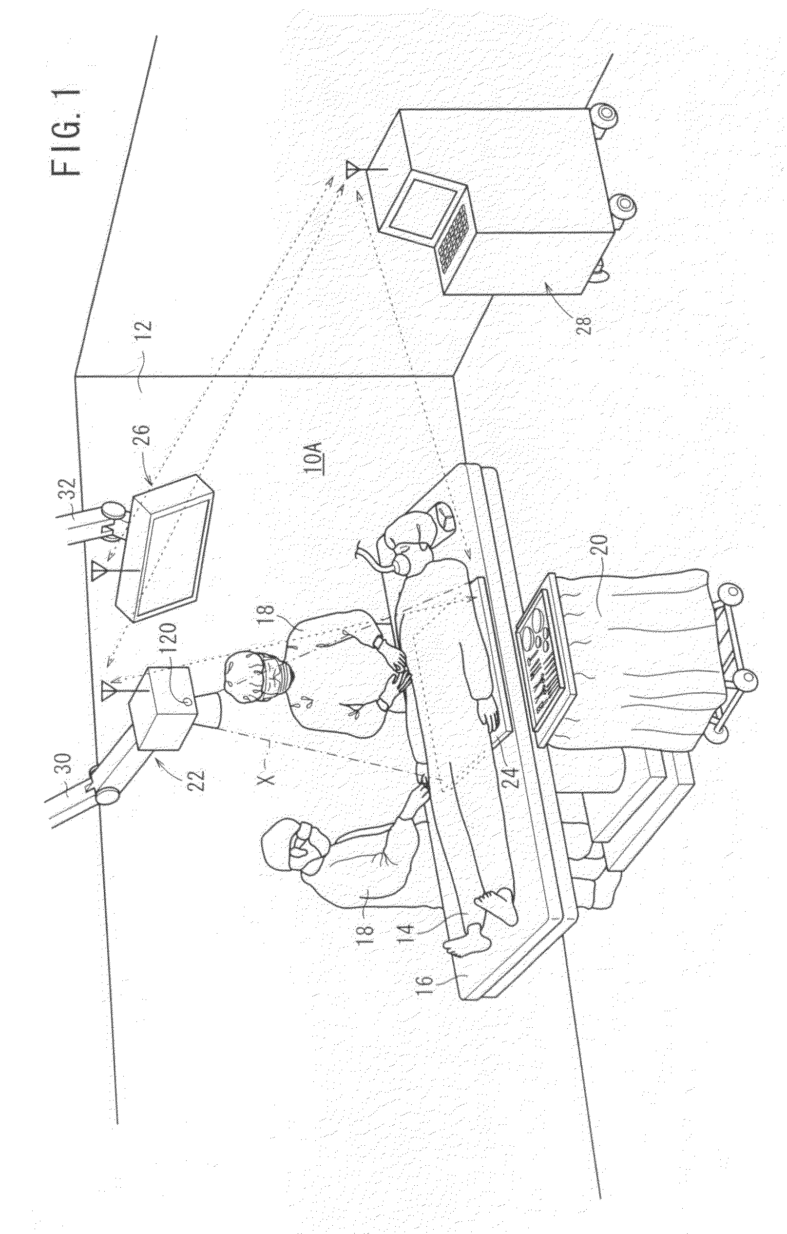
[0032]As shown in FIG. 1, an operating room 12 incorporates a radiation image capturing system 10A according to the present invention. The operating room 12 has, in addition to the radiation image capturing system 10A, a surgical table (bed) 16 for a patient 14 to lie thereon, and an instrument table 20 disposed on one side of the surgical table 16 for placing thereon various tools and instruments to be used by surgeons 18 operating on the patient 14. The surgical table 16 is surrounded by various apparatus required for performing surgical operations, including an anesthesia apparatus, an aspirator, an electrocardiograph, a blood pressure monitor, etc.

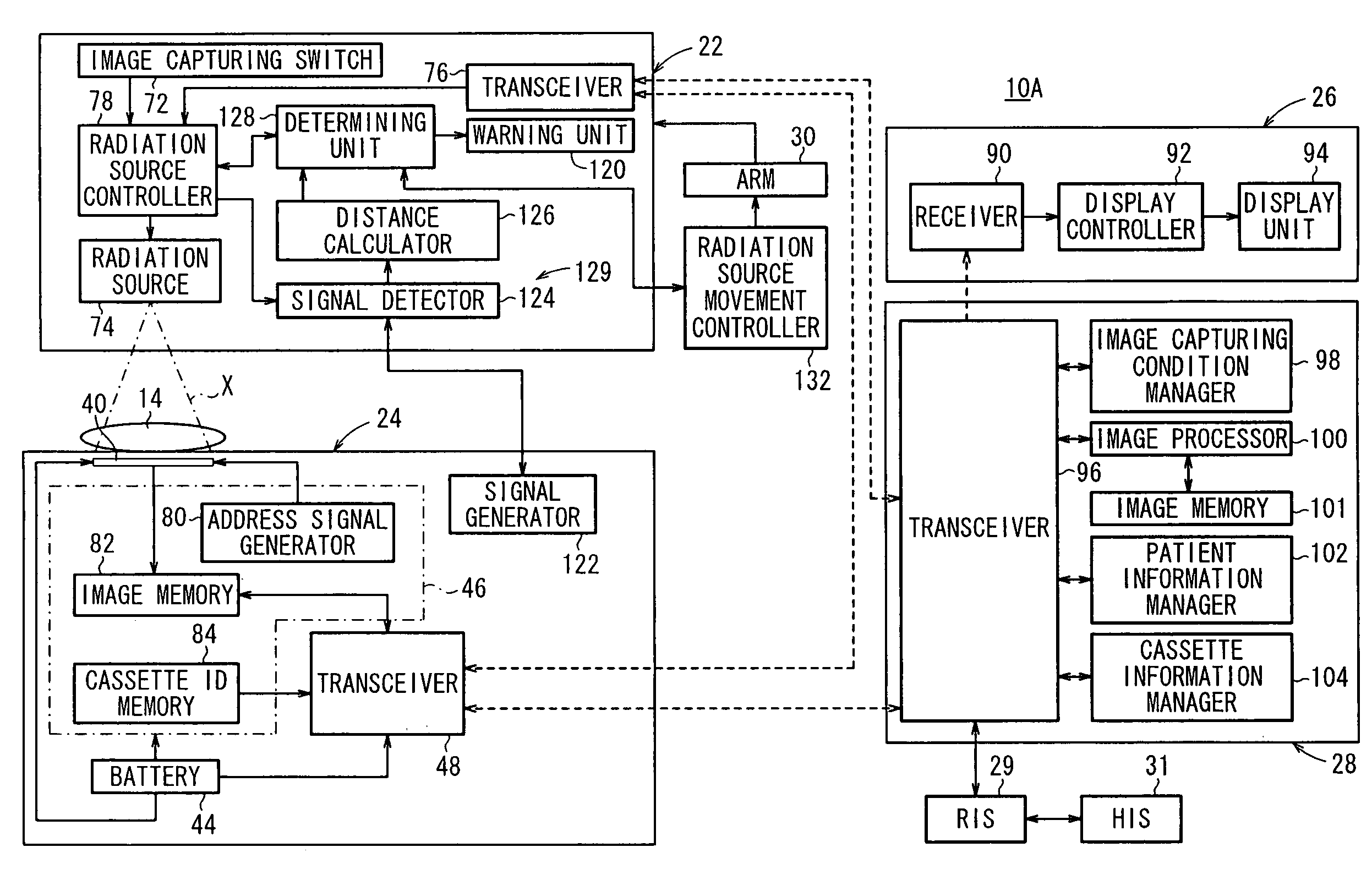
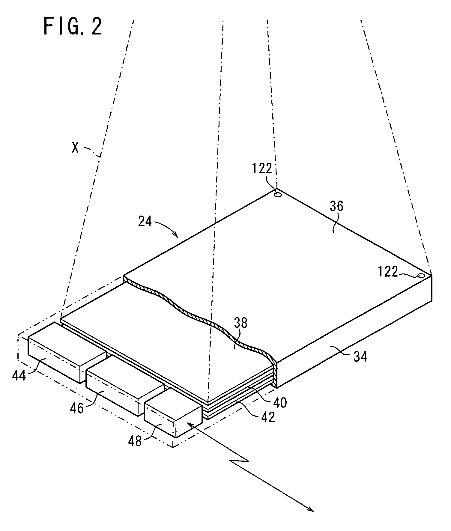
[0033]The radiation image capturing system 10A includes an image capturing apparatus 22 for irradiating the patient 14 as a subject with radiation X at a dose according to image capturing conditions, a radiation detecting cassette 24 housing therein a radiation detector 40 (see FIGS. 2 through 6) for detecting radiation X that has pass...

third embodiment

[0103]A radiation image capturing system 10C according to the present invention will be described below with reference to FIGS. 11 through 13.

[0104]The radiation image capturing system 10C according to the third embodiment is different from the radiation image capturing systems 10A, 10B according to the first and second embodiments (see FIGS. 1 through 10) in that the radiation detecting cassette 24 has a display unit (display means) 136 for indicating its own position.

[0105]The radiation image capturing system 10C is available in two types. One of the types, which is shown in FIG. 11, is similar to the radiation image capturing system 10A according to the first embodiment except for the display unit 136 incorporated in the radiation detecting cassette 24.

second embodiment

[0106]The other type, which is shown in FIG. 12, is similar to the radiation image capturing system 10B except for the display unit 136 incorporated in the radiation detecting cassette 24.

[0107]As shown in FIG. 13, the display unit 136 comprises an LED, for example, disposed on the irradiated surface 36 in any one of the four corners of the casing 34 of the radiation detecting cassette 24. Based on an indication instruction signal sent from the transceiver 96 of the console 28 (see FIGS. 11 and 12) to the transceiver 48 by way of wireless communications, or sent from the transceiver 96 via the transceiver 76 to the transceiver 48 by way of wireless communications, the LED is energized to emit light, thereby indicating the position of the radiation detecting cassette 24, to the surgeons 18 or the radiological technician in the operating room 12.

[0108]Since the display unit 136 indicates the present position of the radiation detecting cassette 24 to the surgeons 18 or the radiologica...


PUM

PropertyMeasurementUnit
distanceaaaaaaaaaa
magnetic fieldsaaaaaaaaaa
distance calculatoraaaaaaaaaa

Abstract

A signal detector detects signals transmitted from signal generators disposed in a radiation detecting cassette, and a distance calculator calculates the distance between a radiation source and a radiation detector based on the signals detected by the signal detector. A determining unit determines whether the detected distance matches a predetermined distance from the radiation source to the radiation detector when a radiation image is captured. If the detected distance does not match the predetermined distance, the determining unit outputs, to a warning unit, a warning signal indicating that the detected distance does not match the predetermined distance, and also outputs a control signal for equalizing the detected distance with the predetermined distance, to a radiation source movement controller.

Description

CROSS-REFERENCE TO RELATED APPLICATIONS[0001]The present application claims priority from Japanese Patent Application Nos. 2007-197950, filed Jul. 30, 2007, and 2008-172108, filed Jul. 1, 2008, the contents of both of which are herein incorporated by reference in their entirety.BACKGROUND OF THE INVENTION[0002]1. Field of the Invention[0003]The present invention relates to a radiation image capturing system having a radiation conversion panel for detecting a radiation that has passed through a subject and converting the detected radiation into radiation image information.[0004]2. Description of the Related Art[0005]In the medical field, there have widely been used radiation image capturing apparatus which apply a radiation to a subject and guide the radiation that has passed through the subject to a radiation conversion panel, which captures a radiation image from the radiation. Known forms of the radiation conversion panel include a conventional radiation film for recording a radia...

Claims


Application Information

Patent Timeline
Patent Type & Authority Patents(United States)
IPC IPC(8): G01N23/04A61B6/08G01T1/24H05G1/64
CPCA61B6/4233A61B6/4476A61B6/4494A61B6/588A61B6/5282A61B6/4488A61B6/4423
Inventor KITO, EIICHITANABE, TSUYOSHIYOSHIMI, TAKUYAKUWABARA, TAKESHIUETA, KAZUHARUIRIUCHIJIMA, MAKOTOOHTA, YASUNORI
Owner FUJIFILM CORP
Why Eureka
Try Eureka