
Rotating electrical machine or alternator and method of manufacturing rotor core used in the same

a technology of rotating electrical machines and alternators, which is applied in the direction of magnetic circuit rotating parts, forging/pressing/hammering apparatus, and shape/form/construction of magnetic circuits, etc., can solve the problems of deteriorating efficiency and increasing magnetic resistance, and achieve the effect of ensuring sufficient magnetic performan

Inactive Publication Date: 2010-06-15
HITACHI LTD
View PDF20 Cites 9 Cited by
  • Summary
  • Abstract
  • Description
  • Claims
  • Application Information

AI Technical Summary

Benefits of technology

The present invention provides a rotor core structure for a rotating electrical machine or alternator that reduces the likelihood of claws opening in the radial direction during high-speed rotation. This is achieved by joining the claw-equipped core and the yoke together using plastic flow or mechanical integration. This reduces the air gap between the claws and stator core, improving magnetic performance and ensuring efficient operation.

Problems solved by technology

This leads to another problem that magnetic resistance is increased in a magnetic path extending from the claw-equipped cores to the stator core and efficiency is deteriorated.

Method used


Image

  • Rotating electrical machine or alternator and method of manufacturing rotor core used in the same
  • Rotating electrical machine or alternator and method of manufacturing rotor core used in the same
  • Rotating electrical machine or alternator and method of manufacturing rotor core used in the same

Examples


Embodiment Construction

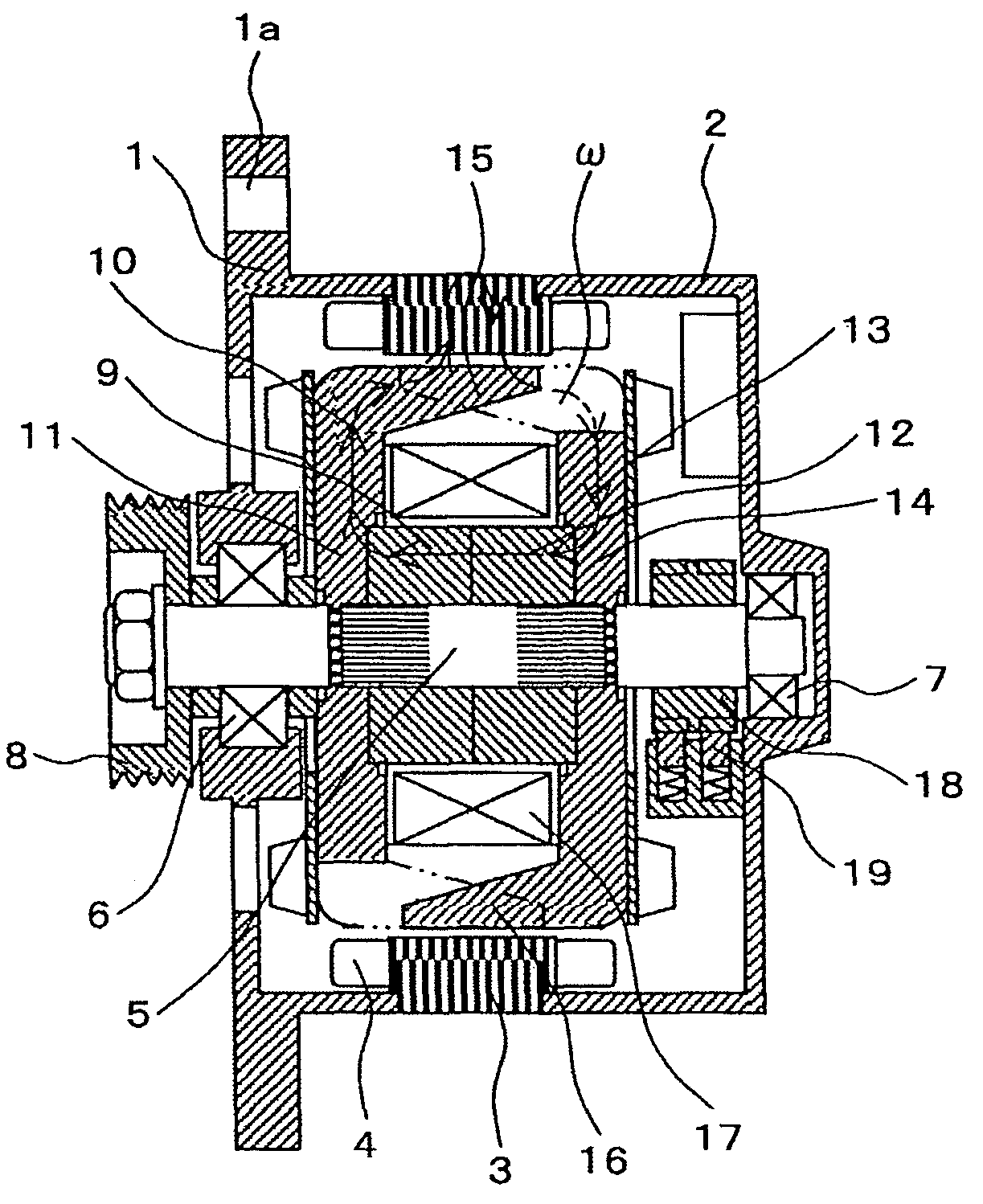
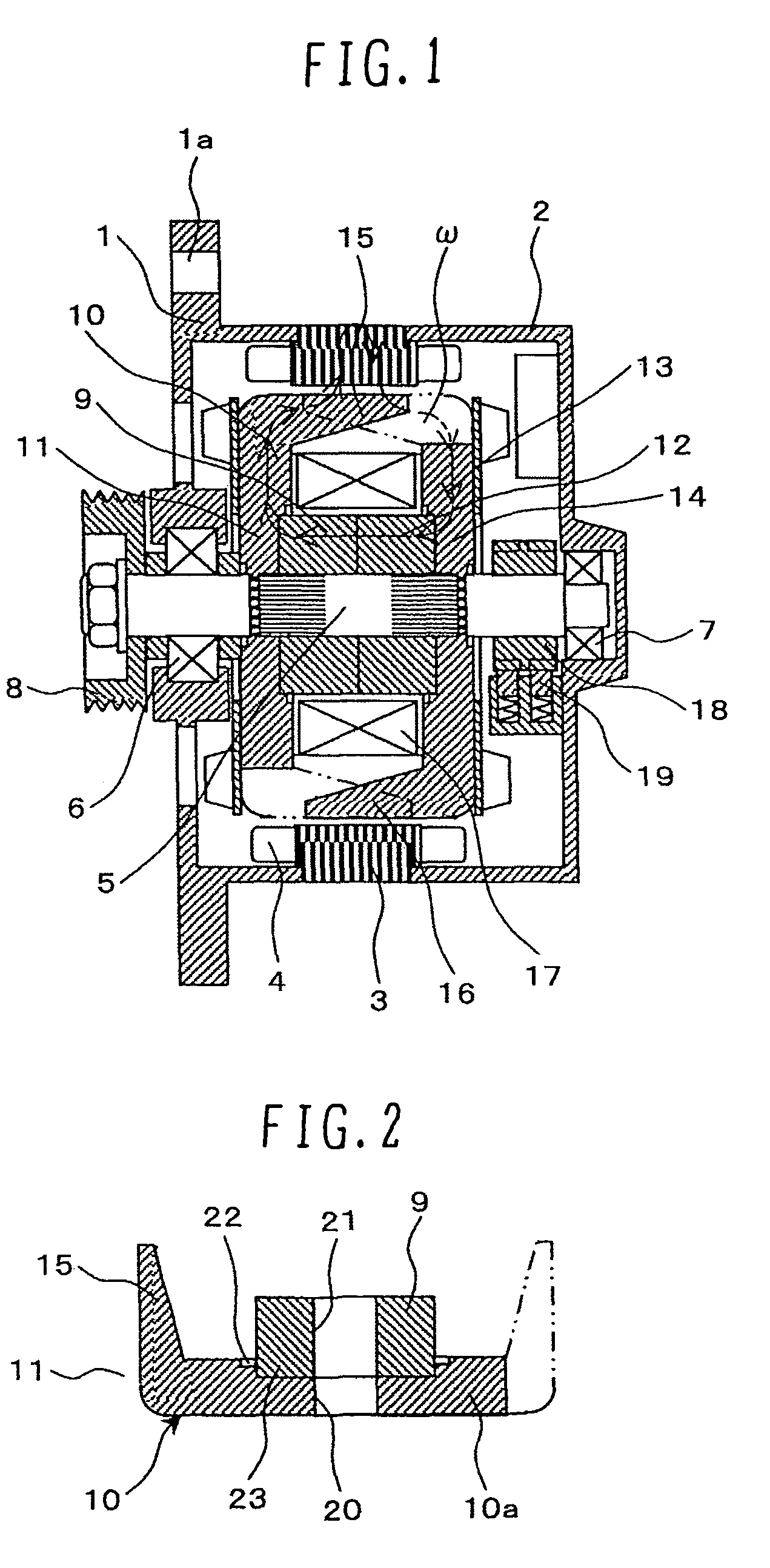
[0032]One example of a vehicular alternator will be described below as a typical example of a rotating electrical machine according to one embodiment of the present invention. FIG. 1 is a longitudinal sectional view of the vehicular alternator.

[0033]A stator core 3 is held between a front housing 1 and a rear housing 2. The front housing 1, the rear housing 2, and the stator core 3 are fixed together by tightening screws and nuts (not shown) to apply a strong force in the direction in which the front housing 1 and the rear housing 2 grip the stator core 3 between them. The front housing 1 includes a flange 1a which is used to fix the alternator to a bracket provided on an engine block (not shown). The stator core 3 has a plurality of teeth formed along an entire inner periphery facing the rotor side, and stator coils 4 are wound over the teeth. Three-phase AC voltages are induced in the stator coils 4 with the rotation of magnetized rotor cores 11 and 14 (described later).

[0034]A ro...


PUM

PropertyMeasurementUnit
groove widthaaaaaaaaaa
boss widthaaaaaaaaaa
plastic flowaaaaaaaaaa

Abstract

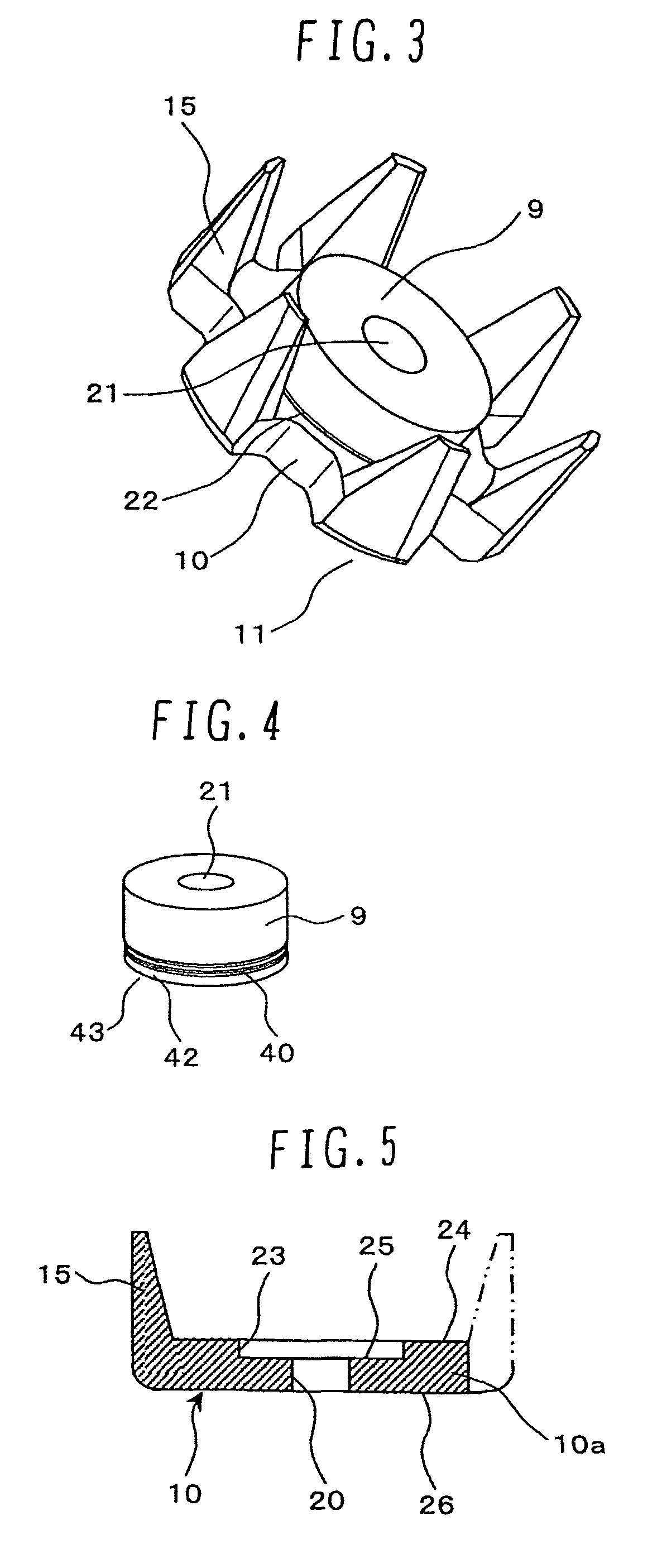
A rotor core which has relatively high rigidity, can ensure sufficient magnetic performance, and can be produced at a cheaper cost with a relatively small-scale facility. A claw-equipped core and a yoke are manufactured separately. After fitting the yoke to a fitting portion formed in the claw-equipped core, a part of the claw-equipped core in the vicinity of the fitting portion is axially pressed to plastically flow into an annular groove formed in the yoke, thereby integrally joining the claw-equipped core and the yoke to each other. Thus, a large-scaled manufacturing facility is not required, and claws of the claw-equipped core are hard to open in the radial direction even under the action of a centrifugal force during high-speed rotation. A stator core and the claws of the claw-equipped core can be positioned closer to each other, and deterioration of magnetic performance can be avoided.

Description

BACKGROUND OF THE INVENTION[0001]1. Field of the Invention[0002]The present invention relates to a rotating electrical machine or an alternator and a method of manufacturing a rotor core used in the rotating electrical machine or the alternator.[0003]2. Description of the Related Art[0004]In a known alternator, plate-like rotor cores are disposed at opposite ends of a cylindrical yoke which is disposed in the inner peripheral side, and a plurality of claws are axially projected from outer peripheries of the rotor cores in alternately interdigitated relation. A shaft is inserted within the yoke. Further, because of the necessity of arranging a field coil between inner peripheries of the claws and an outer periphery of the yoke, the yoke is divided into a plurality of pieces and the divided yoke pieces are fixed to each other after arranging the field coil in place.[0005]Patent Document 1 (JP-B-61-000979) discloses a rotor core structure in which claw-equipped cores and a yoke are con...

Claims


Application Information

Patent Timeline
Patent Type & Authority Patents(United States)
IPC IPC(8): H02K1/22
CPCH02K1/243B21K1/28H02K15/022H02K5/08Y10T29/49012B21K25/00
Inventor HARADA, KOJI
Owner HITACHI LTD
Learn More