
Remote control system and method thereof, remote control device and device targeted for control

a remote control and wireless signal technology, applied in the field of remote control systems using wireless signals, can solve the problems of wasteful to include the identifier in the remote control signal, inability to guarantee that the signal will never operate any types of devices of any device manufacturer, and inability to assign the unique identifier to all devices of all device manufacturers in advan

Inactive Publication Date: 2010-06-15
NEC CORP
View PDF5 Cites 14 Cited by
  • Summary
  • Abstract
  • Description
  • Claims
  • Application Information

AI Technical Summary

Benefits of technology

[0006]According to a conventional technique described in Patent Document 1, a remote operation on a plurality of controlled target devices can be performed by using one remote control device. Further, a device desired to be remote-controlled can be selected from among the controlled target devices by an intuitive operation of directing the remote control device toward the controlled target device, desired to be selected and depressing the remote control key of the remote control device. Further, after the controlled target device has been selected, the remote control signal is transmitted from the omni-directional antenna. Accordingly, there is an advantage that during the remote operation, the user does not need to direct the remote control device to the controlled target device. However, the following problem arises.
[0009]Accordingly, it is an object of the present invention to provide a remote control system which can reduce the frequency of antenna switching, and which can avoid an unexpected other device from being remote-controlled.
[0079]Further, according to the present invention, after the search signal has been transmitted through the directional antenna, switching to the omni-directional antenna is performed to transmit the remote control signal. Thus, the frequency with which antenna switching is performed in the remote control device can be reduced.
[0081]Further, according to the present invention, the dynamically assigned identifier does not need to allow unique identification of all devices of all manufacturers. Thus, the number of bits of the identifier does not need to be large. For this reason, a data length of the remote control signal itself can be correspondingly reduced. Thus, an efficiency of using the electric wave and an efficiency of using a memory for storing the identifier can be improved.

Problems solved by technology

However, the following problem arises.
The reason for this is that though a signal generated by a certain remote control program should generally operate only a certain specific controlled target device associated with the program, there is no guarantee that the signal will never operate any types of devices of any device manufacturers.
Since there is no organization for assigning an identifier unified to all devices, it is impossible to assign the unique identifier to all devices of all device manufacturers, in advance.
It is wasteful to include the identifier in the remote control signal, for transmission.

Method used


Image

  • Remote control system and method thereof, remote control device and device targeted for control
  • Remote control system and method thereof, remote control device and device targeted for control
  • Remote control system and method thereof, remote control device and device targeted for control

Examples


first embodiment

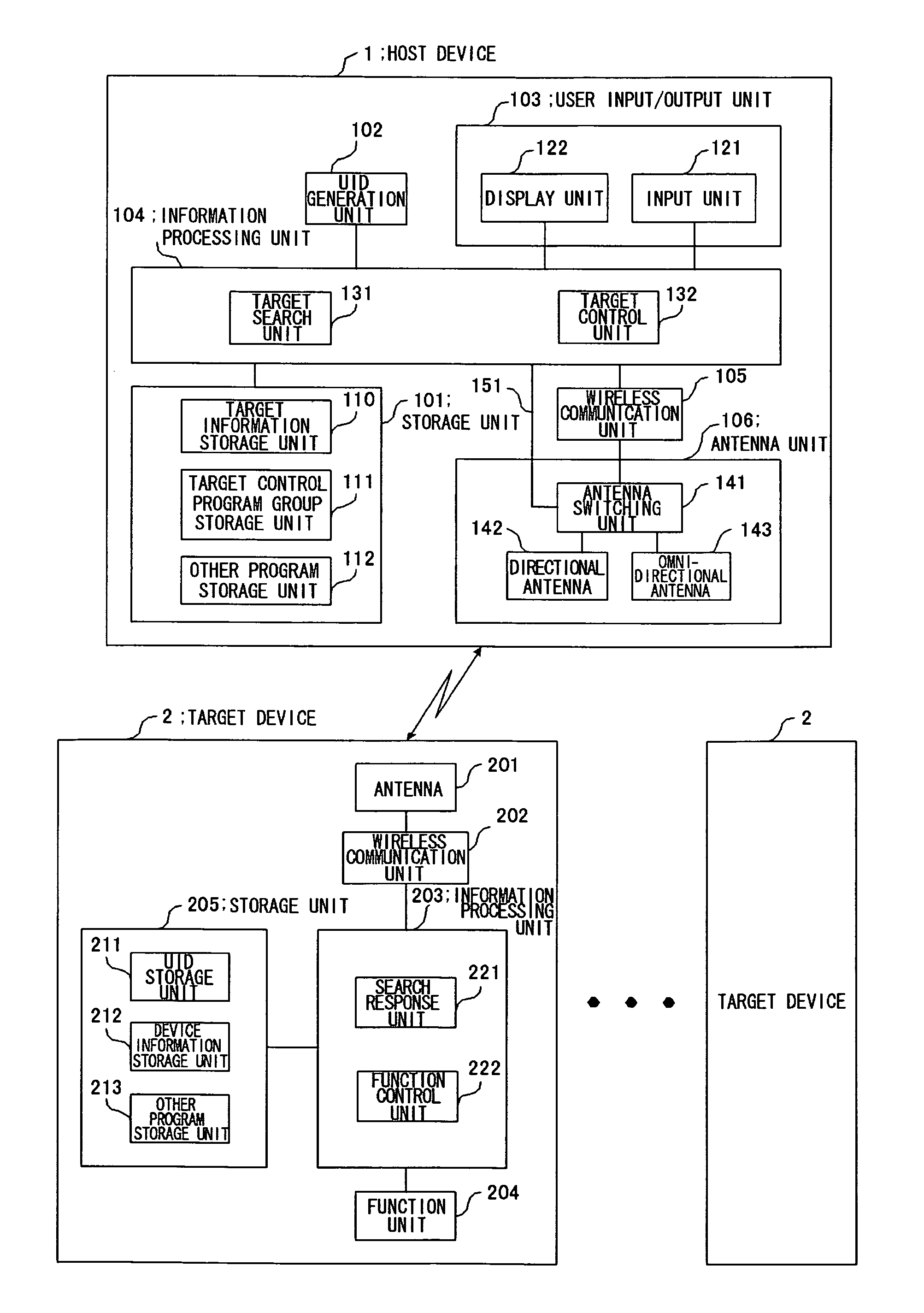
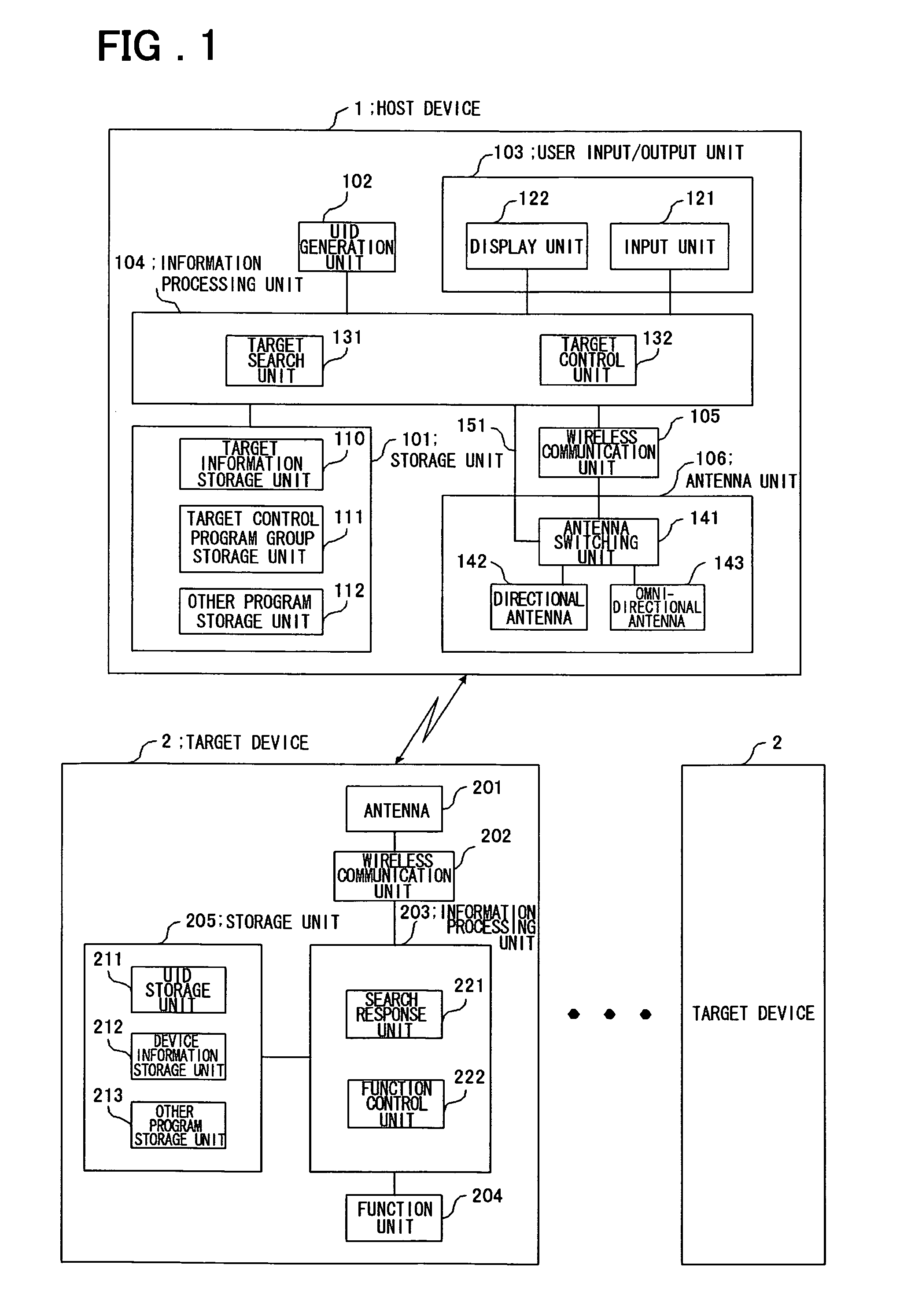
[0097]Referring to FIG. 1, a remote control system according to a first embodiment of the present invention includes a host device 1 that is a remote control device and a plurality of target devices 2 that are controlled target devices.

[0098]The host device 1 comprises a memory unit 101, a UID (Unique Identity) generation unit 102, a user input / output unit 103, an information processing unit 104, a wireless communication unit 105, and an antenna unit 106. The memory unit 101 includes a target control program group memory unit 111 and other program memory unit 112. The user input / output unit 103 includes an input unit 121 and a display unit 122. The information processing unit 104 includes a target search unit 131 and a target control unit 132. The antenna unit 106 includes an antenna switching unit 141, a directional antenna 142, and an omni-directional antenna 143.

[0099]The directional antenna 142 is the antenna of which antenna sensitivity in a certain specific direction is marked...

second embodiment

[0134]Referring to FIG. 7, a remote control system according to a second embodiment of the present invention is different from the remote control system in the first embodiment in following respects. In this system, the information processing unit 104 of the host device 1 includes a target separating unit 133. The information processing unit 203 of each target device 2 includes a UID rewriting unit 223. Then, when a target device 2 is searched for by the host device 1 using the directional antenna 142 and when response signals are then returned from a plurality of the target devices 2, UID reassignment is performed so that different UIDs are assigned to the plurality of the target devices 2, respectively. Then, one of the plurality of the target devices is selected by the user.

[0135]When the response signals to the target device search signal transmitted from the target search unit 131 are returned from the plurality of the target devices 2, the target separating unit 133 takes over...

third embodiment

[0157]Referring to FIG. 10, a remote control system according to a third embodiment of the present invention is different from the remote control system in the second embodiment shown in FIG. 7 in that the information processing unit 104 of the host device 1 includes a target narrowing-down unit 134 in place of the target separating unit 133.

[0158]The target narrowing-down unit 134 takes over the processing from the target search unit 131 when the response signals to the target device search signal transmitted from the target search unit 131 are returned from a plurality of the target devices 2. First, the target narrowing-down unit 134 displays on the display unit 122a a list of the plurality of the target devices 2 that have transmitted the response signals, thereby causing the user to select one of the target devices 2 using an input from the input unit 121. Next, the target narrowing-down unit 134 transmits the identifier reassignment signal including a unique identifier newly g...


PUM


Abstract

In a remote control system, when a user directs a host device of a portable type toward target devices for search and specification, a search signal including a unique identifier (UID) is transmitted from a directional antenna. Each of the target devices stores the UID included in the received search signal in a memory unit, and transmits a response signal including device information on itself from an antenna. The host device identifies one of the target devices based on the device information included in the response signal, runs a control program for the identified target device, and displays an operation screen on a display unit. When the user instructs the remote operation on the operation screen, the host device transmits a remote control signal including the UID from the omni-directional antenna. When the target device receives the remote control signal including the UID that matches with the UID stored in the memory unit, the target device controls a function unit according to the remote control signal.

Description

FIELD OF THE INVENTION[0001]The present invention relates to a remote control system using a wireless signal. More specifically, the invention relates to a system in which using one remote control device and the wireless signal, one of controlled target devices is selectively remote-controlled.BACKGROUND OF THE INVENTION[0002]An example of a conventional remote control system of this type is described in Patent Document 1. In this remote control system described in Patent Document 1, two antennas composed by directional and omni-directional antennas are provided for a remote control device. Assume that, in order to perform remote control of a certain controlled target device, a user determines an orientation of the remote control device so that the desired certain controlled target device is identified in a direction in which sensitivity of the directional antenna becomes best and that the user presses a remote control key. Then, the remote control device transmits a signal requesti...

Claims


Application Information

Patent Timeline
Patent Type & Authority Patents(United States)
IPC IPC(8): G08C19/00G06F13/00H04Q9/00
CPCG08C17/02G08C2201/71G08C2201/30
Inventor WATANABE, MITSUHIRO
Owner NEC CORP
Learn More