Electronically steered phased array blade antenna assembly

a phased array blade and antenna assembly technology, applied in the direction of antennas, elongated active element feeds, antenna feed intermediates, etc., can solve the problems of reducing the effective radiated power performance, reducing the gain, and thus reducing the standoff distance between the jammer and the target, so as to improve the lateral target coverage, improve the effect of effective radiated power and improve the matching

Inactive Publication Date: 2010-06-15
THE UNITED STATES OF AMERICA AS REPRESENTED BY THE SECRETARY OF THE NAVY
View PDF6 Cites 0 Cited by
  • Summary
  • Abstract
  • Description
  • Claims
  • Application Information

AI Technical Summary

Benefits of technology

[0009]The antenna design comprises a two-element phased array blade antenna (PAB) assembly which provides improved lateral target coverage with an increased effective radiated power and exhibits a smooth null-free unidirectional lateral antenna pattern. Each blade is coupled to the RF switching device and 90 degree hybrid coupler combination by a semi-rigid Radio Frequency (RF) cable through a sub-resonant choke balun for improved impedance matching.
[0010]This antenna design provides a superior antenna input Voltage Standing Wave Ratio (VSWR), smooth pattern coverage and large antenna gain. Moreover, broadband antenna performance is achieved with a unique antenna blade design that not only improves the usable frequency range of the antenna, but also provides for a light weight construction that is required for most airborne antenna systems.
[0011]Another unique feature of this antenna array design is the fact that it does not require any impedance matching networks since the antenna blade construction features a nominal input impedance of fifty ohms. This feature is a major antenna design simplification directly reducing construction cost, increasing reliability and also reducing RF insertion loss. The transformation of an unbalanced RF input coaxial cable to a balanced configuration is accomplished with two sub-resonant choke baluns, each made out of a coiled semi-rigid RF feed cable. This approach gives the lowest cost antenna balun implementation with more than adequate performance and most of all maximum design simplicity. The innovative antenna blade design provides a well-behaved antenna input impedance characteristic that covers approximately 22% of the bandwidth around the center or target design frequency.

Problems solved by technology

However, most of the antennas, especially those covering lower frequency bands, provide less than optimal pattern coverage and thus reduced Effective Radiated Power (ERP) performance.
Although the '083 patent reference provides added benefits of good impedance stability versus frequency and stable monotonic antenna pattern characteristics in proximity to an irregular ground plane, the overall design approach imposes the following limitations: the design has an inherent bidirectional antenna pattern vice a unidirectional antenna pattern, a lower amount of radiated power is directed towards the intended target as a result of the bidirectional antenna pattern, the antenna pattern is fixed to radiate symmetrically from the host platform vice a left only or right only radiation pattern, the phased array blade antenna described in the '083 patent reference is not capable of switching the direction of radiation in response to control commands and most importantly, the reference results in a lower gain and thus a shorter standoff distance between a jammer and a target.
There are no known airborne antenna designs in the prior art that will operate in the desired frequency range, at the desired power level, respond to main lobe directional control commands and increases the standoff distance between the jammer and the target.

Method used


Image

  • Electronically steered phased array blade antenna assembly
  • Electronically steered phased array blade antenna assembly
  • Electronically steered phased array blade antenna assembly

Examples


Embodiment Construction

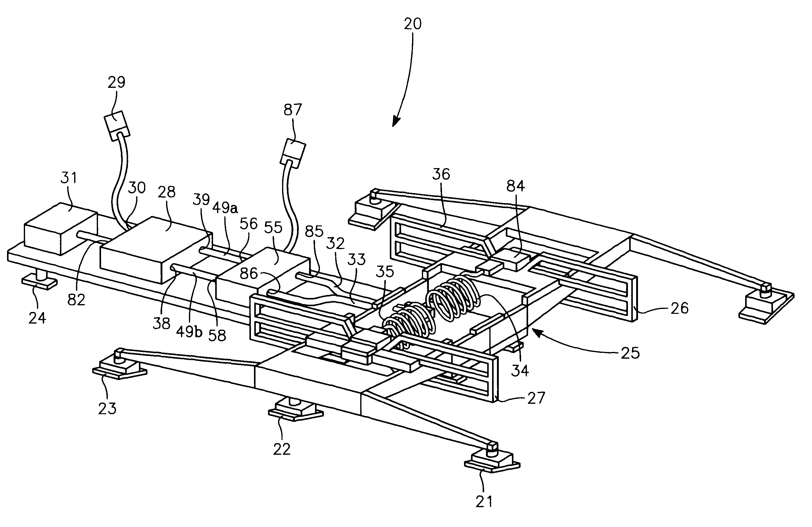
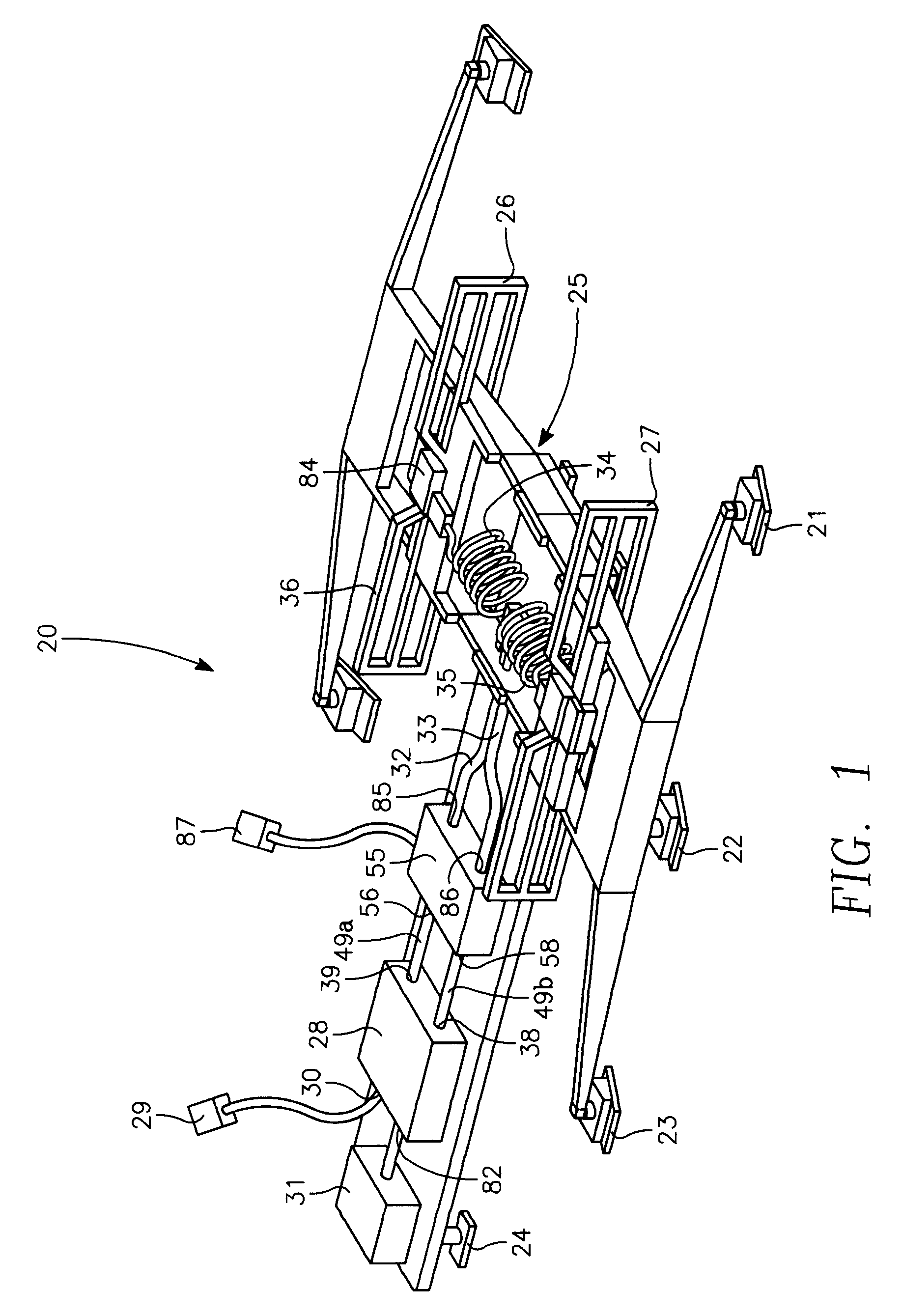
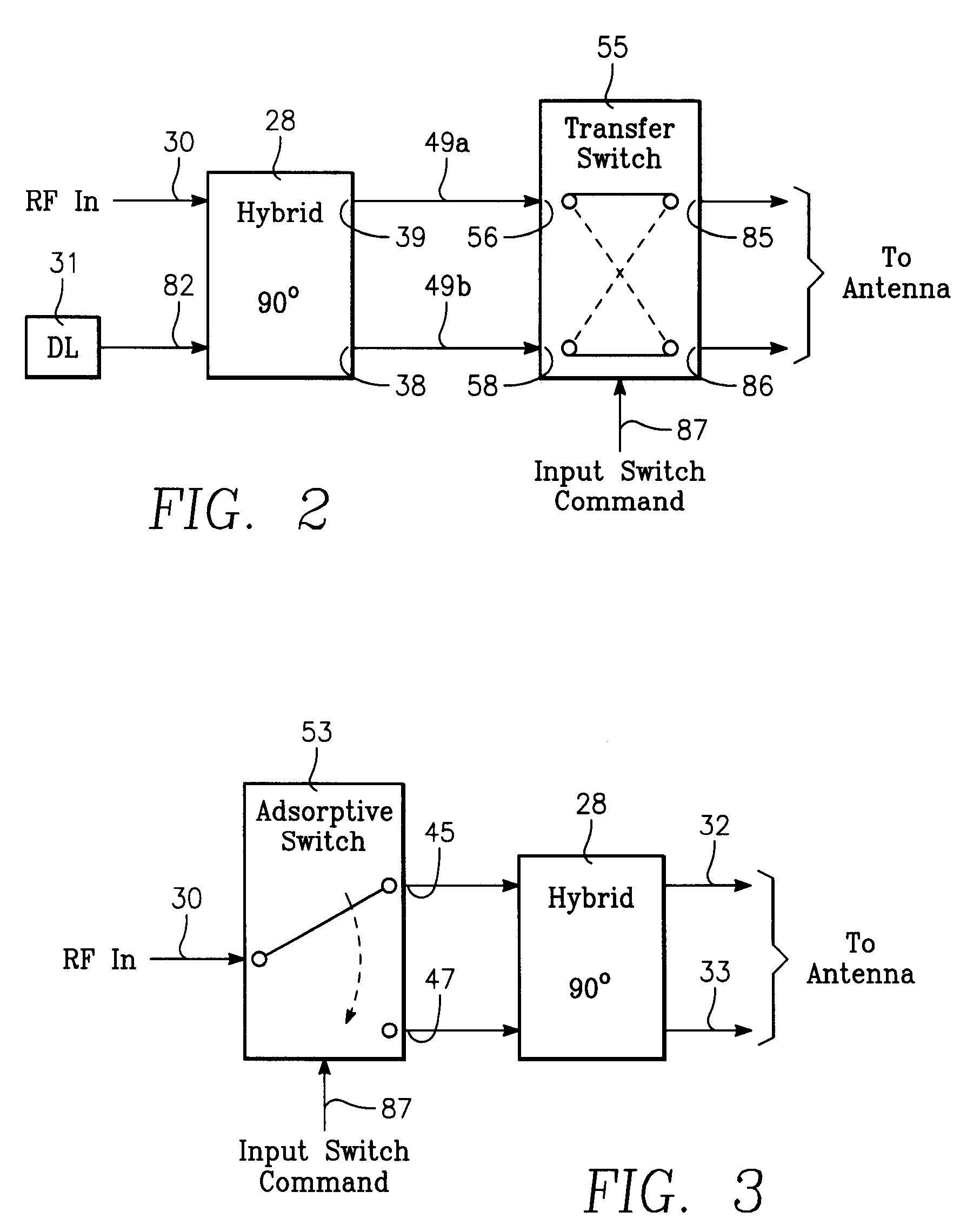
[0018]The preferred embodiment of the electronically steered phased array blade (ESPAB) antenna assembly 20 is shown in FIG. 1. The ESPAB antenna assembly 20 fits within the constraints of a radome intended for use on an aircraft. Clamps 21, 22, 23 and 24 are mounted on a structure made of a dielectric substrate 25 and placed as shown to anchor the ESPAB antenna assembly 20 to the radome. The quantity of clamps mounted on the dielectric substrate 25 can be increased in order to achieve the desired stability.

[0019]The ESPAB antenna assembly 20 of FIG. 1 contains two modified dipole antenna elements 26 and 27 spatially separated by a distance approximated by λ / 4. This design requires that the dipole element separation be set to accommodate the center frequency of interest. Due to the radome's internal spatial constraints, the dipole element spacing deviation from λ / 4, within + / −20%, will also provide acceptable performance of the antenna assembly 20.

[0020]The RF signal that feeds the ...


PUM


Abstract

An antenna design, having two symmetrical phased array blade antenna elements which provide improved lateral target coverage with an increased effective radiated power and exhibits smooth null-free unidirectional antenna patterns. The direction of the unidirectional antenna pattern is dictated by a switching command under control of a user. Each blade antenna element is coupled to a 90-degree hybrid coupler and an RF switching device by a semi-rigid RF cable. Each blade antenna element is also connected to a sub-resonant choke balun for improved impedance matching and resultant distortion-less antenna patterns.

Description

STATEMENT REGARDING FEDERALLY SPONSORED RESEARCH OR DEVELOPMENT[0001]The invention described herein may be manufactured and used by or for the government of the United States of America for governmental purposes without the payment of any royalties thereon or therefore.BACKGROUND OF THE INVENTION[0002]1. Field of the Invention[0003]The present invention relates generally to an electronically steered radio frequency beam transmitted by a phased array blade antenna assembly for use on an airborne platform whose mission is electronic warfare. The electronically steered radio frequency beam is dynamically directed to either the left or right side of the airborne platform in order to directionally maximize the power of the radiated radio frequency signal.[0004]2. Description of the Prior Art[0005]The industry has a number of airborne antennas used with different airborne amplifiers and covering a broad range of frequencies. However, most of the antennas, especially those covering lower f...

Claims


Application Information

Patent Timeline
Patent Type & Authority Patents(United States)
IPC IPC(8): H01Q21/12
CPCH01Q9/16H01Q21/062H01Q9/32H01Q9/30
Inventor ADAMSKI, PIOTR ROMAN
Owner THE UNITED STATES OF AMERICA AS REPRESENTED BY THE SECRETARY OF THE NAVY
Why Eureka
Try Eureka