
Disk array system and rebuild method thereof

a disk array system and disk array technology, applied in the field of redundancy disk array systems, can solve the problems of reducing the access performance of the disk array system during the period of rebuilding, and achieve the effects of reducing the redundancy level, increasing the capacity of the disk, and increasing the time for rebuilding

Active Publication Date: 2010-06-15
NEC ASIA PACIFIC PTE LTD
View PDF45 Cites 26 Cited by
  • Summary
  • Abstract
  • Description
  • Claims
  • Application Information

AI Technical Summary

Benefits of technology

[0011]In a redundant disk array system having a RAID level 5 or the like, data in a failed disk (replacement disk) is prepared using disks other than the failed disk at the time of disk rebuilding, it takes time to perform the rebuilding. With an increased capacity of disks in particular, the time for the rebuilding is increased. Further, during the rebuilding, a redundancy level is reduced. The access performance of the disk array system during the period of the rebuilding is thus degraded.
[0012]Accordingly, it is an object of the present invention to provide a disk array system and a method that achieve a higher speed operation for rebuilding of a replacement disk and shorten a period during which the redundancy level is reduced.
[0013]Other object of the present invention is to provide a disk array system and a method that suppress degradation of access performance during preparation of data on a replacement disk.
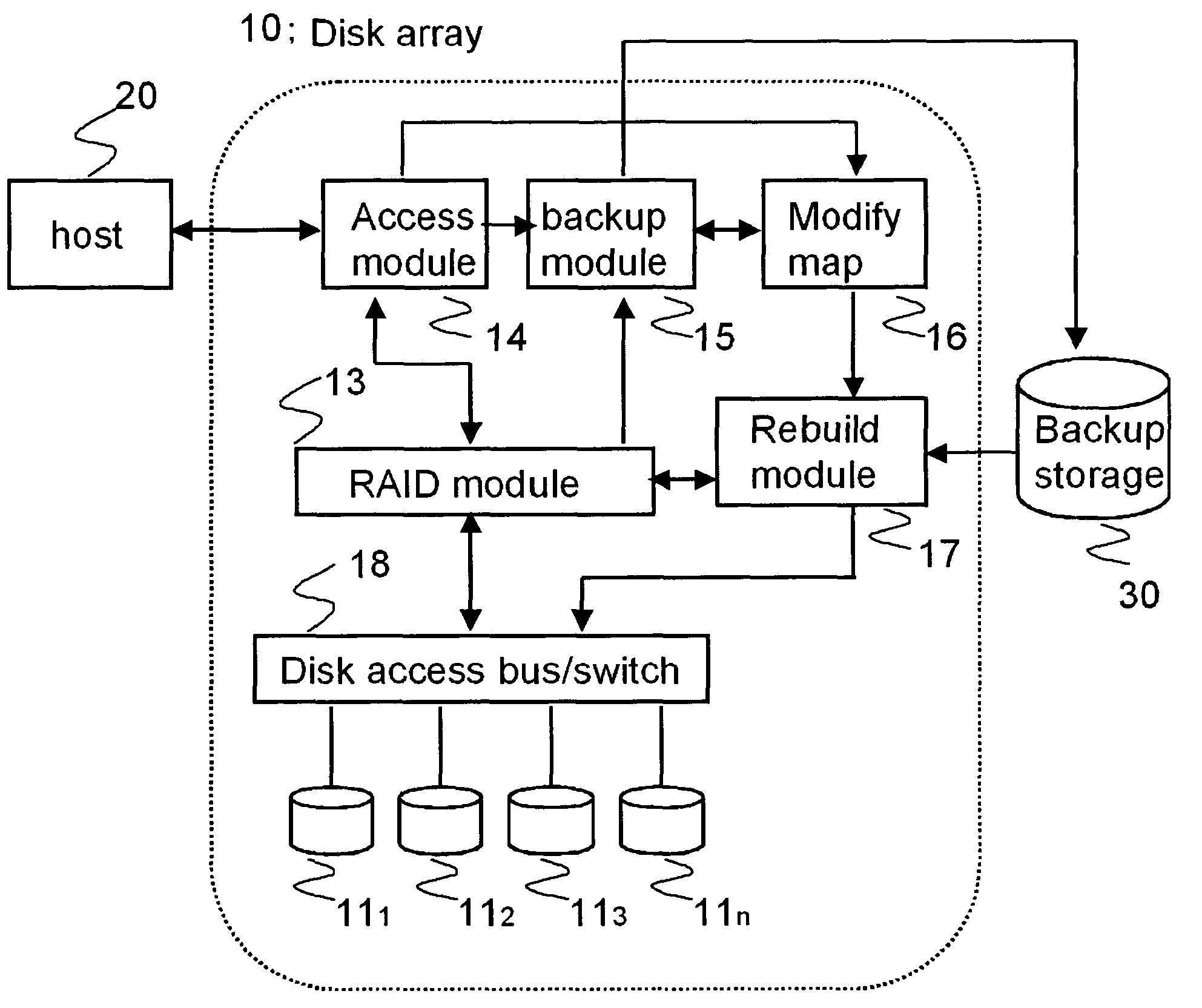
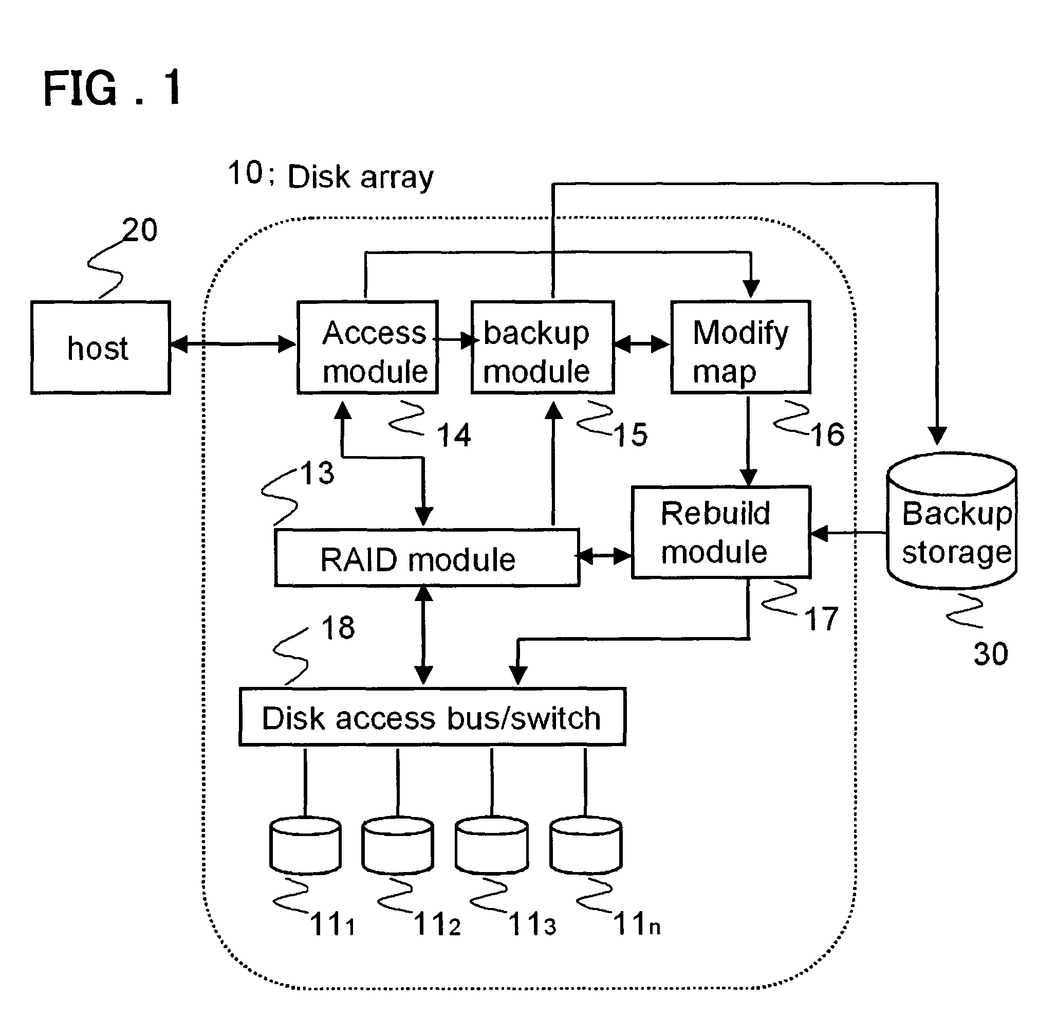
[0025]In the present invention, a disk access bus / switch for data transfer between said backup storage device and said replacement disk drive is provided and the rebuilding of said replacement disk drive from said backup storage is performed through the rebuild module provided in parallel with a RAID module for performing a normal read / write access to said disk array and said disk access bus / switch, thereby said rebuilding operation of said replacement disk drive being prohibited from influencing a normal access by said RAID module said to said disk array.
[0028]According to the present invention, the degradation in the performance does not occur during the rebuilding. Accordingly, the rebuilding does not need to be performed at a low speed. For this reason, a rebuilding period can be reduced. Then, according to the present invention, due to a reduction in the rebuilding period, a probability of occurrence of a failure in a second disk during the rebuilding can be reduced.

Problems solved by technology

The access performance of the disk array system during the period of the rebuilding is thus degraded.

Method used


Image

  • Disk array system and rebuild method thereof
  • Disk array system and rebuild method thereof
  • Disk array system and rebuild method thereof

Examples


embodiment

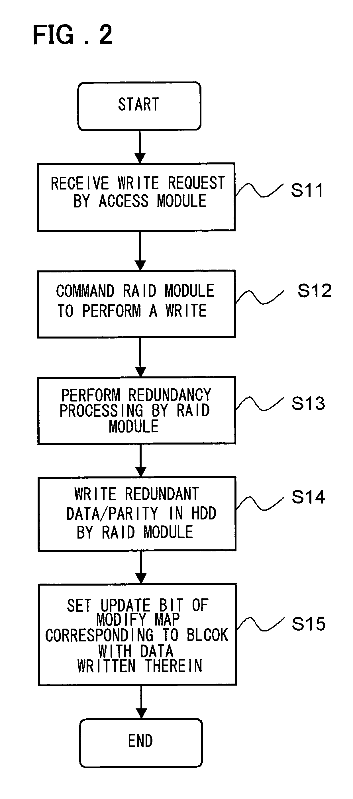
[0045]FIG. 2 is a flow diagram for explaining write processing at a normal time in this embodiment. The access module 14 receives a WRITE (write) request from the host 20 (at step S11). Incidentally, though no particular limitation is imposed, the HDD (Hard Disk Drive) is employed for each of the disks 111 to 11n of FIG. 1 in FIGS. 2 through 8.

[0046]The access module 14 commands the RAID module 13 to perform a WRITE (transmits the WRITE command) (at step S12).

[0047]The RAID module 13 performs redundancy processing (parity generation) of data at a parity generator not shown (at step S13).

[0048]The RAID module 13 writes data and a parity which have been made redundant into a disk (HDD) (at step S14).

[0049]The access module 14 sets the update bit (update bit) of the modify map 16 corresponding to the logical block with data written therein (at step S15).

[0050]FIG. 3 is a flow diagram for explaining READ processing at a normal time in this embodiment. The access module 14 receives a REA...


PUM


Abstract

Disclosed is a disk array system which includes a plurality of disks constituting a disk array and a backup storage for backing up data in the disk array and performs control so that when a failed disk among the disks constituting the disk array is replaced with the replacement disk, restoration of data in the replacement disk is performed using the backup device.

Description

FIELD OF THE INVENTION[0001]The present invention relates to a redundant disk array system. More specifically, the invention relates to a disk array system and a rebuild method thereof.BACKGROUND OF THE INVENTION[0002]Disk arrays are also referred to as RAIDs (Redundancy Arrays of Independent (Inexpensive) Disks) and have a configuration in which a plurality of disks are arranged in an array form. By appending redundancy data to data, reliability of the disk array is improved. The RAID includes a RAID0 in which by striping, for example, a plurality of disks are used as if it were one disk, a RAID1 in which using mirroring, the same data is written to a plurality of disks, a RAID5 in which by recording data and parities on a plurality of disks, fault tolerance is improved, and the like. Among these disks, in the RAID5, parity information for error correction is generated when the data is written to the disks. This parity information is distributed across and written to the disks with...

Claims


Application Information

Patent Timeline
Patent Type & Authority Patents(United States)
IPC IPC(8): G06F11/00
CPCG06F11/1092G06F11/1458G06F11/1456
Inventor YAMATO, JUNICHIKAJIKI, YOSHIHIRO
Owner NEC ASIA PACIFIC PTE LTD
Learn More