Tire and wheel noise reducing device and system

a technology of noise reduction device and noise reduction device, which is applied in the field of vehicle noise reduction, can solve problems such as attenuation of sound, and achieve the effects of reducing tire noise, reducing low-frequency energy, and dampening pressure flows

Inactive Publication Date: 2010-06-22
TIRE ACOUSTICS LLC
View PDF42 Cites 10 Cited by
  • Summary
  • Abstract
  • Description
  • Claims
  • Application Information

AI Technical Summary

Benefits of technology

[0010]A device for reducing tire noise can absorb and reduce low-frequency energy that produces tire noise. The device can absorb sound shock waves by alternately pressurizing and depressurizing a vessel having an air flow-resistant barrier. The flow-resistant barrier dampens pressure flows into and out of the vessel to dampen shock waves that pass through the barrier. Additionally, friction in the flow-resistant element of the vessel converts sound energy into heat, thus attenuating the sound. Additionally, a hybrid device can have elements of an air flow-resistant cavity absorber and elements of a frictional absorber.
[0011]According to one aspect, a tire noise absorbing device can comprise multiple layers of an air flow-resistant material with multiple openings in each layer. The layers can be assembled such that the openings of each layer are offset with respect to overlapped portions of an adjacent layer. The offset openings allow air to pass through the layers when the tire is stationary and the layers are slack, thereby allowing complete inflation of the tire. The overlapping layers can be coupled to a wheel or directly to a tire to form loops of overlapped elements. When a car is put into motion and the tire begins to rotate, centrifugal force forces the overlapped layers outward and together to seal the air passages of the openings and to form an air flow-resistant cavity between the wheel and the cloth layers. Specifically, the inner layer is forced outward against the outer layer, the openings in the inner layer are sealed by the outer layer, and the openings in the outer layer are sealed by the inner layer. The layers restrict air flow between a tire (outer) side of the layers and a wheel (inner) side of the layers, thereby absorbing low-frequency energy noise as air passes through the layers.
[0012]In a further embodiment, the layers can slide against each other and create friction when displaced by low-frequency shock waves. The resulting friction can absorb additional low-frequency energy noise by dissipating such the shock waves via heat produced by the friction.
[0013]Increasing the absorption of low-frequency energy also can reduce the perceived high-frequency tire noise without compromising tread design or tire adhesion. The design can fit easily into an existing tire and can be mounted to existing wheels or to a tire during or after the manufacturing process.
[0014]Other aspects include variations of the position and coupling means of attaching the device to the wheel or tire. For example, the device can be coupled at a centrally located position on the wheel or with various profiles that provide different shaped flow-resistant cavities. Still other aspects include multiple elements with overlapping or interlocking ends to create the flow-resistant cavity. These elements are forced outward by centrifugal force and create a cavity when the overlapping or interlocking portions move together to create a device that resists air flow. In addition, the overlapping portions can create friction when displaced by shock waves to further absorb low frequency noise. Yet another aspect includes creating multiple flow-resistant air cavities by layering two or more flow-resistant elements around a wheel or tire. These multiple flow-resistant air cavities can absorb shock waves and can improve noise reduction. Further aspects involve a tubular, crescent, or curved element positioned on the wheel or tire, thus creating a single flow-resistant cavity. Such an element in the tubular shape also can be used in sections to create multiple flow-resistant cavities around the wheel.

Problems solved by technology

Additionally, friction in the flow-resistant element of the vessel converts sound energy into heat, thus attenuating the sound.

Method used


Image

  • Tire and wheel noise reducing device and system
  • Tire and wheel noise reducing device and system
  • Tire and wheel noise reducing device and system

Examples


Embodiment Construction

[0036]Exemplary embodiments will be described with reference to FIGS. 1-13 in which the same reference numerals represent similar elements.

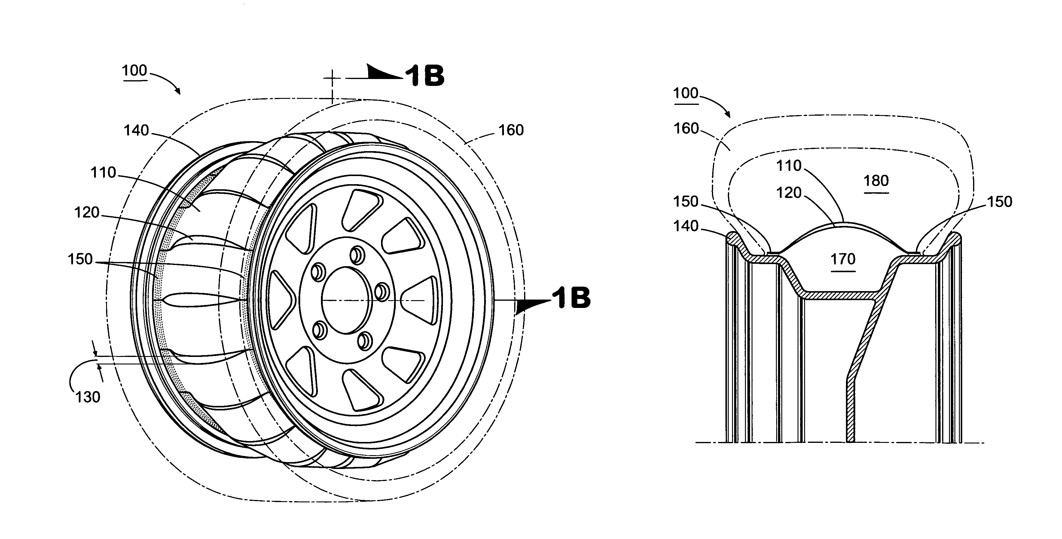
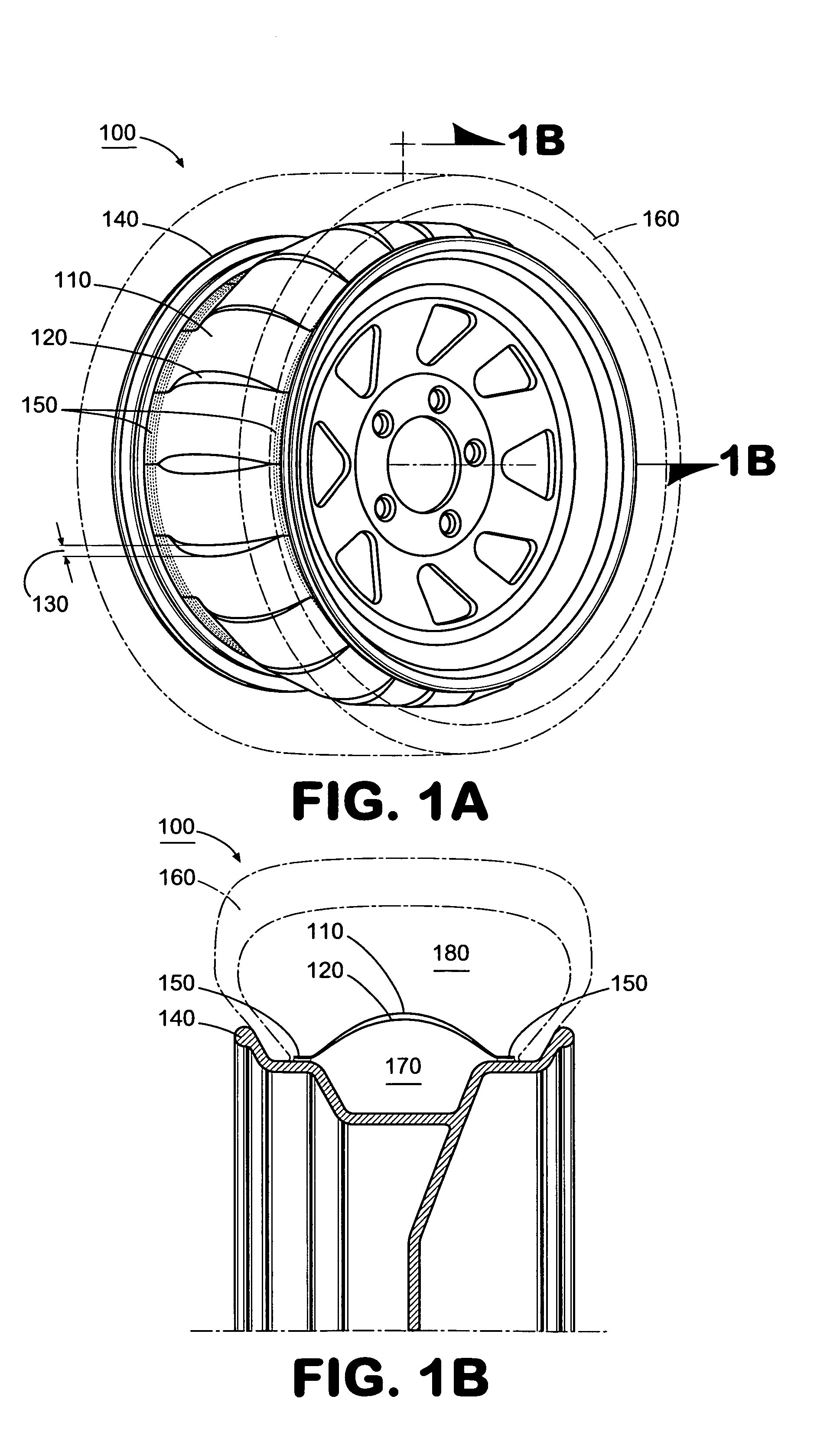
[0037]FIG. 1A is a perspective view illustrating a tire noise absorbing system 100 comprising a flow-resistant barrier disposed on a wheel 140 for a tire 160 according to an exemplary embodiment. FIG. 1B is a cross-sectional view of the exemplary system 100 illustrated in FIG. 1A. As shown in FIGS. 1A and 1B, the system 100 comprises multiple, overlapped layers 110, 120 of material, which form an acoustic flow-resistant barrier. The layer 110 comprises an outer layer with reference to the wheel 140, and the layer 120 comprises an inner layer with reference to the wheel 140. The overlapping layers 110, 120 are coupled to the wheel 140 along their edges at location 150 to form loops of overlapped material. In other words, the layers 110, 120 are wrapped around the wheel 140 and coupled to both sides of the wheel 140 at locations 150. The location 1...


PUM


Abstract

A system for dissipating sound shock waves within a vehicle tire includes a wheel upon which a tire is mounted to create an internal air chamber defined by the wheel and the tire. A flow-resistant barrier is coupled to the wheel or the tire and defines an air cavity within the internal air chamber. The barrier comprises a material that provides an acoustical resistance to sound shock waves passing therethrough. The air cavity defined by the barrier has a volume such that air within the cavity offers relatively small impedance to the passage of shock waves through the barrier and into the air cavity. The barrier also can produce frictional heat when displaced by a shock wave, thereby converting energy of the shock wave to heat to reduce noise associated therewith.

Description

RELATED APPLICATION[0001]This patent application claims priority under 35 U.S.C. §119 to U.S. Provisional Patent Application No. 60 / 694,018, entitled “Tire and Wheel Noise Absorbing Device and System,” filed Jun. 24, 2005. The complete disclosure of the above identified priority application is hereby fully incorporated herein by reference.TECHNICAL FIELD[0002]The present invention relates generally to reducing vehicle noise from tires and wheels. Specifically, the present invention relates to a sound-reducing device disposed in the internal air chamber created by a tire and a wheel upon which the tire is mounted.BACKGROUND OF THE INVENTION[0003]When car tires contact a road surface, they generate considerable noise. At speeds above 25 mph in certain vehicles, tire noise can be greater than all other sources of automotive noise combined. Accordingly, car and tire manufacturers spend large amounts of resources every year on research and development to reduce tire noise.[0004]Tire nois...

Claims


Application Information

Patent Timeline
Patent Type & Authority Patents(United States)
IPC IPC(8): G10K11/16
CPCB60C19/002Y10T152/1054Y10T152/10495B60C5/20B60C5/00
Inventor FOWLER-HAWKINS, SANFORD ELLIOT
Owner TIRE ACOUSTICS LLC
Why Eureka
Try Eureka