Microstrip filter including resonators having ends at different coupling distances

a technology of resonators and microstrips, applied in the field of filters, can solve the problems of ineffective techniques, microstrip filters constructed of conventional metals, and suffer a much higher loss than other technologies, and achieve the effect of simple design changes

Inactive Publication Date: 2010-06-22
SUPERCONDUCTOR TECHNOLOGIES INC
View PDF10 Cites 2 Cited by
  • Summary
  • Abstract
  • Description
  • Claims
  • Application Information

AI Technical Summary

Benefits of technology

[0011]One feature of the present invention is that the resonator is designed to have both ends accessible from one side of the resonator. Because of the current flow in a resonator, orienting the two ends of the resonator toward the same side allows the primary and secondary coupling to be added or subtracted from one another through relatively simple design changes. Another feature includes arranging and configuring a first end of the resonator with a substantially larger interface to the adjacent resonator than the second end of the resonator. The primary coupling between the resonator is generally associated with the first larger interface end of the resonator to the adjacent resonator. The secondary coupling is generally associated with the second smaller interface end of the resonator to the adjacent resonator, but the secondary coupling may also be assisted by an additional coupling strip.

Problems solved by technology

However, microstrip filters constructed of conventional metals suffer a much higher loss than other technologies (e.g., such as waveguide, dielectric resonator, combline, etc.), and especially in very narrow bandwidth filters.
However, the techniques may not be effective (using the same structure), when the required bandwidth of the filter becomes large.
In some cases, the spacing may become too small from manufacturability point of view, i.e., lithography, sensitivity, yield, etc.

Method used


Image

  • Microstrip filter including resonators having ends at different coupling distances
  • Microstrip filter including resonators having ends at different coupling distances
  • Microstrip filter including resonators having ends at different coupling distances

Examples


Embodiment Construction

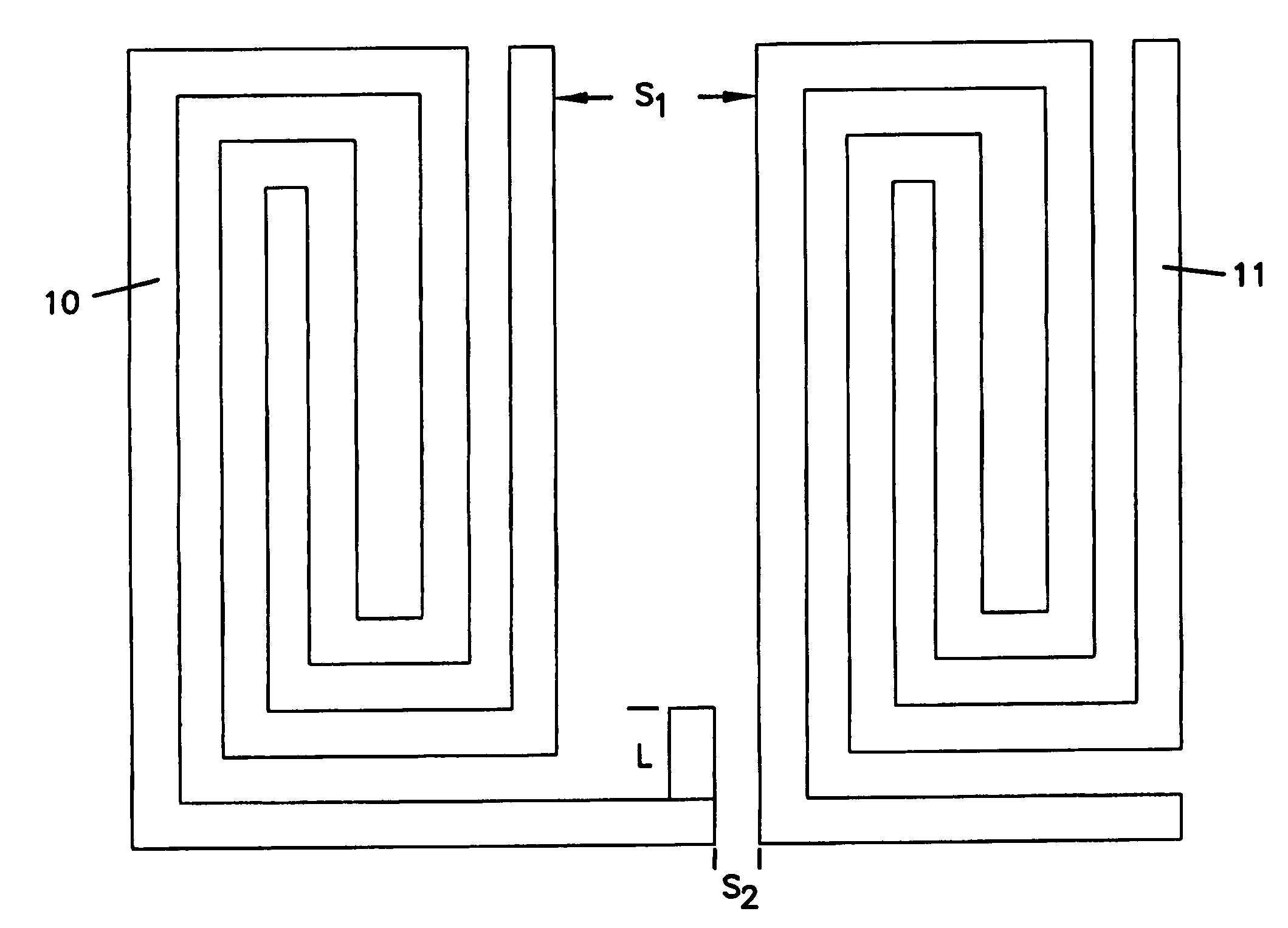
[0027]The principles of this invention apply to the filtering of electrical signals. The preferred apparatus and method of the present invention provides for control of placement of transmission zeroes to provide greater skirt rejection and optimize the transmission response curve of the filter. Means are provided to increase or decrease the coupling between resonator elements in order to control the zeroes. A preferred use of the present invention is in communication systems and more specifically in wireless communications systems. However, such use is only illustrative of the manners in which filters constructed in accordance with the principles of the present invention may be employed.

[0028]The present invention provides for a method and apparatus to provide appropriate coupling between resonators in an HTS microstrip filter. The present invention utilizes primary and secondary couplings between a pair of resonators. With a given spacing, the primary coupling is fixed, while the ...


PUM

PropertyMeasurementUnit
lengthaaaaaaaaaa
dielectricaaaaaaaaaa
distancesaaaaaaaaaa

Abstract

A method and apparatus to provide appropriate coupling between resonators in an HTS microstrip filter are disclosed. Primary and secondary couplings between a pair of resonators are utilized. With a given spacing, the primary coupling is fixed, while the secondary coupling can have different magnitude. In addition, the secondary coupling can have the same phase or opposite phase as the primary coupling. With different combinations, large or small bandwidth filters can be made without very small or very large spacing between resonators. The same cross coupling layout configuration may be designed to achieve either positive or negative results.

Description

[0001]This application is being filed as a PCT International patent application in the name of Conductus, Inc., a U.S. national corporation, applicant for the designation of all countries except the US, and Shen Ye, a resident of the U.S. and a citizen of Canada, applicant for the designation of the U.S. only, and claims priority to U.S. application Ser. No. 60 / 362,596, filed Mar. 8, 2002.FIELD OF THE INVENTION[0002]This invention generally relates to the field of filters. More particularly, it relates to the field of microwave band filters. Still more particularly, it relates to the field of very-narrow band, microstrip, superconductive band-pass filters.BACKGROUND OF INVENTION[0003]Narrowband filters are particularly useful in the communications industry and particularly for wireless communications systems which utilize microwave signals. At times, wireless communications have two or more service providers operating on separate bands within the same geographical area. In such inst...

Claims


Application Information

Patent Timeline
Patent Type & Authority Patents(United States)
IPC IPC(8): H01P1/203H01B12/02H01P1/205
CPCH01P1/20381H01P1/20336H01P1/203
Inventor YE, SHEN
Owner SUPERCONDUCTOR TECHNOLOGIES INC
Why Eureka
Try Eureka