Secondary grinding section for an orifice plate of a grinding machine

a technology of grinding section and orifice plate, which is applied in the direction of peelers, solid separation, kitchen equipment, etc., can solve the problems of affecting the quality of meat produced by the grinding machine, the wear of the parts, and the various parts of the grinding machine are subject to tremendous force and rotational stresses, so as to achieve the effect of reducing width, increasing size, and high shear

Active Publication Date: 2010-06-29
PROVISUR TECHNOLOGIES INC
View PDF17 Cites 10 Cited by
  • Summary
  • Abstract
  • Description
  • Claims
  • Application Information

AI Technical Summary

Benefits of technology

[0010]In one aspect of the grinding machine of the present invention, a grinding head defines an axial bore, and the bore has a plurality of flutes. The width of the flutes is variable across the length of the bore, and is dimensioned to perform various functions. For example, the flutes may be dimensioned to generally decrease in width from the upstream end of the bore to the downstream end of the bore, or may be increased in size in areas of high shear, or may be adjusted across the angles of the bore, as the situation demands. Not only does the variable dimensioning of flutes within the bore of the grinding head control the flow of material through the head, the provisions of flutes in the head is also cost-effective since flutes can be cast along with head rather than being machined in the head or requiring additional parts, such as bars, to be welded to the head.
[0011]In another aspect of the grinding machine of the present invention, assembly of the grinding head is simplified and made consistent between grinder operators. Because the grinder head must be frequently disassembled and reassembled for cleaning, ease of assembly and consistent reassembly is desirable. One aspect of the grinding machine of the present invention includes provision of a stop portion within the bore of the grinder head so that the orifice plate can be inserted to the correct depth within the bore with each reassembly sequence. In another aspect of the grinding machine of the present invention, a tensioning device is mounted between the feed screw and knife assembly for application of constant pressure, urging the knife assembly against the orifice plate. This ensures that the knife assembly contacts the orifice plate with sufficient force to grind material as desired, but prevents premature wear of the grinder parts.
[0012]In an aspect of the grinding machine of the present invention that eases disassembly of the grinder head for cleaning, recesses such as slots are provided on the outer edge of the orifice plate, and corresponding removal recesses may be provided at the adjacent end of the grinder head. The combination of the orifice plate slots and the grinder head recesses allows an operator to insert a tool into one of the grinder head recesses to access an orifice plate slot and apply leverage to the orifice plate, thus removing it from the opening of the head despite any ground material that may have become lodged between the parts. Two or more corresponding orifice plate recesses and grinder head recesses are provided around the diameter of the orifice plate and adjacent grinding head for application of leverage at more than one location.

Problems solved by technology

The quality of meat produced by a grinding machine is limited by its ability to remove hard materials from the useable materials.
Finally, various parts of a grinding machine are subject to tremendous force and rotational stresses, and wear to these parts is expected.
However, the overall cost of grinding machines and various replacement and wear parts is typically very high.

Method used


Image

  • Secondary grinding section for an orifice plate of a grinding machine
  • Secondary grinding section for an orifice plate of a grinding machine
  • Secondary grinding section for an orifice plate of a grinding machine

Examples


Embodiment Construction

[0048]1. Resume

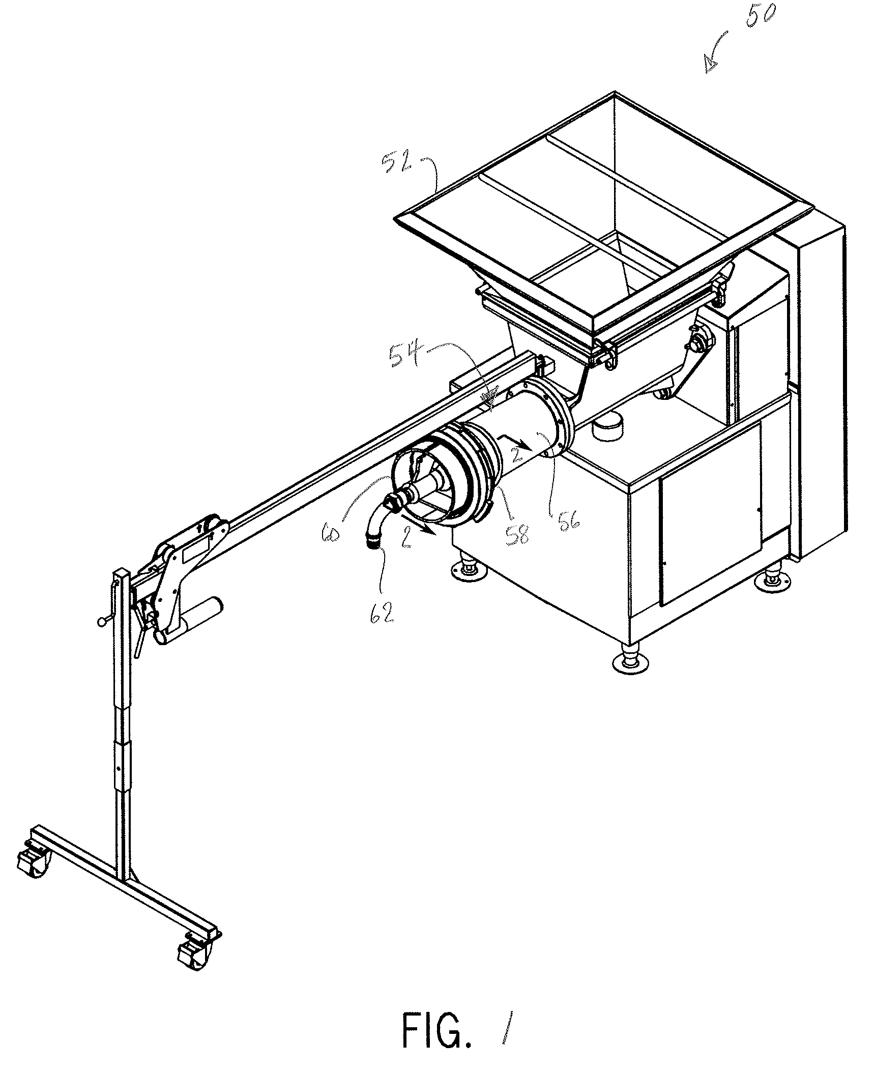
[0049]A grinding machine 50 is generally shown in FIG. 1. Grinding machine 50 has a hopper portion 52 and a grinder portion 54. Grinder portion 54 includes a housing or head 56, a mounting ring 58, a bridge 60, and a collection tube 62.

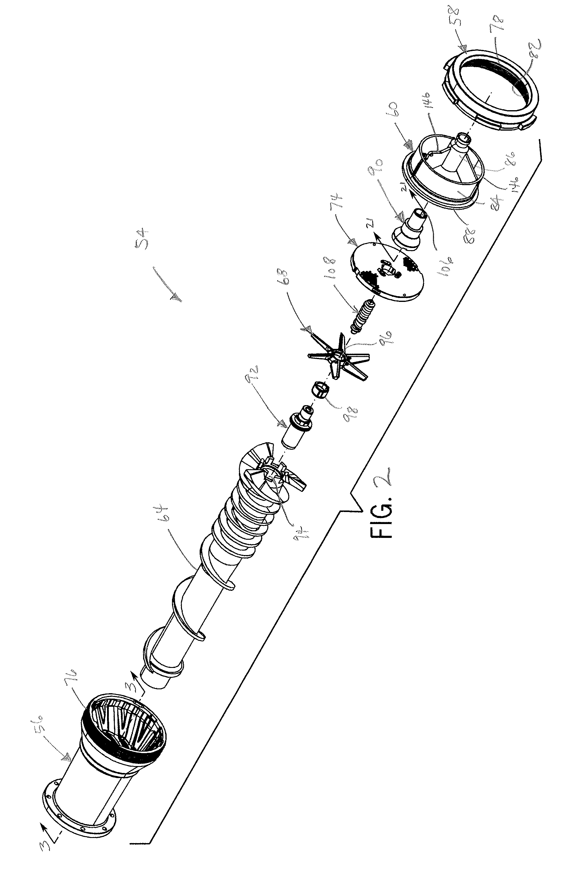
[0050]Referring now to FIG. 2, head 56 is generally tubular and a feed screw 64 is rotatably mounted within head 56 so that, upon rotation of feed screw 64 within head 56, meat or the like is advanced from hopper 52 through the interior of head 56. A knife holder 68 is mounted at the end of, and rotates with, feed screw 64. Knife holder 68 has six arms 70a-f and six knife inserts, one corresponding to each of arms 70a-f, although it is understood that any number of arms and corresponding inserts may be employed.

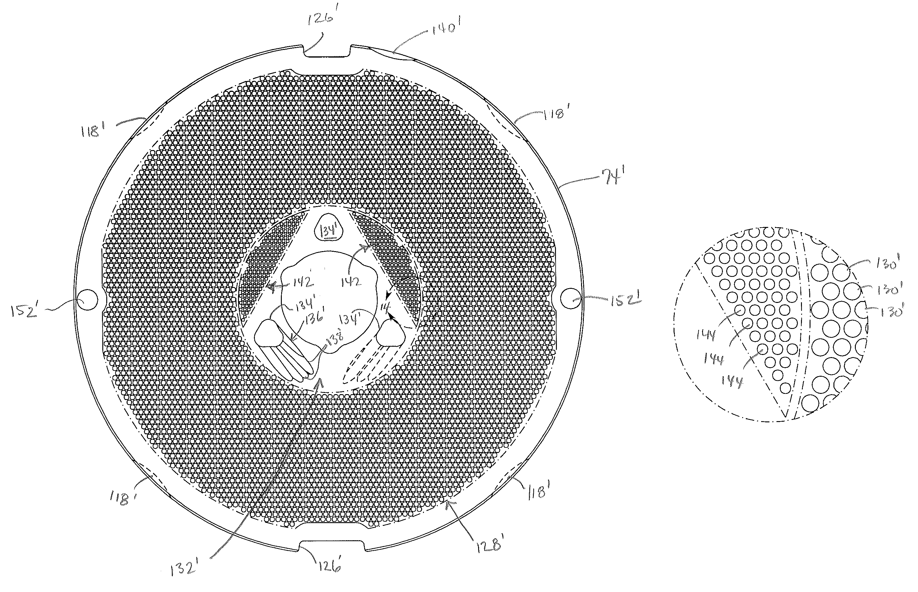
[0051]Referring now to FIG. 3, knife holder 68 is located adjacent an inner grinding surface of an orifice plate 74, which is secured in the open end of head 56 by mounting ring 58 and bridge 60. The knife inserts bear against th...


PUM


Abstract

An orifice plate with an outer grinding section and an inner grinding section is disclosed. The outer grinding section is the main grinding section leading to the main material collection stream, and an additional grinding section is present in the inner section of the orifice plate to remove useable material from material swept toward the center of the plate by the action of a rotating knife assembly on the plate. The useable material obtained at the inner section is also led to the main material collection stream.

Description

CROSS-REFERENCE TO RELATED APPLICATION[0001]This application claims priority under 35 U.S.C. §119(e) to U.S. Provisional Application Ser. No. 60 / 728,473, filed Oct. 20, 2005, the contents of which are hereby incorporated by reference in their entirety.FIELD OF THE INVENTION[0002]The present invention relates to a grinding head of a meat grinder, and more particularly, relates to improved design and function of parts of a grinding head that improve the meat grinding process in terms of ease of disassembly and reassembly, safety, increased quality and output, reduced cost of production of parts, and reduced need for replacement parts.DISCUSSION OF THE RELATED ART[0003]The general structure of grinding machines is well known. Typically, a grinding machine has a hopper into which the material to be ground is placed, a grinder portion, including a grinding head, a mounting ring, a bridge, and a collection tube. A feed screw is located within the grinding head to advance material in the h...

Claims


Application Information

Patent Timeline
Patent Type & Authority Patents(United States)
IPC IPC(8): B02C18/36
CPCB02C18/302B02C18/365B02C2018/308
Inventor ALBRECHT, CHRISTOPHER E.LESAR, NICK J.
Owner PROVISUR TECHNOLOGIES INC
Why Eureka
Try Eureka