Carrier assembly and system configured to commonly ground a header

a header and carrier technology, applied in the direction of connection contact member materials, two-part coupling devices, coupling device connections, etc., can solve the problems of electrical noise generated by signal connections, electrical connectors are challenged with carrying an increased number of electrical signals, and the frequency of electrical signals increases

Inactive Publication Date: 2010-06-29
3M INNOVATIVE PROPERTIES CO
View PDF36 Cites 81 Cited by
  • Summary
  • Abstract
  • Description
  • Claims
  • Application Information

AI Technical Summary

Problems solved by technology

Consequently, electrical connectors are challenged with carrying an increased number of electrical signals, each potentially having increased signal frequency.
However, as signal frequencie

Method used


Image

  • Carrier assembly and system configured to commonly ground a header
  • Carrier assembly and system configured to commonly ground a header
  • Carrier assembly and system configured to commonly ground a header

Examples


Embodiment Construction

[0024]In the following Detailed Description, reference is made to the accompanying drawings, which form a part hereof, and in which is shown by way of illustration specific embodiments in which the invention may be practiced. In this regard, directional terminology, such as “top,”“bottom,”“front,”“back,”“leading,”“trailing,” etc., is used with reference to the orientation of the Figure(s) being described. Because components of embodiments can be positioned in a number of different orientations, the directional terminology is used for purposes of illustration and is in no way limiting. It is to be understood that other embodiments may be utilized and structural or logical changes may be made without departing from the scope of the present invention. The following detailed description, therefore, is not to be taken in a limiting sense, and the scope of the present invention is defined by the appended claims.

[0025]It is to be understood that the features of the various exemplary embodi...


PUM


Abstract

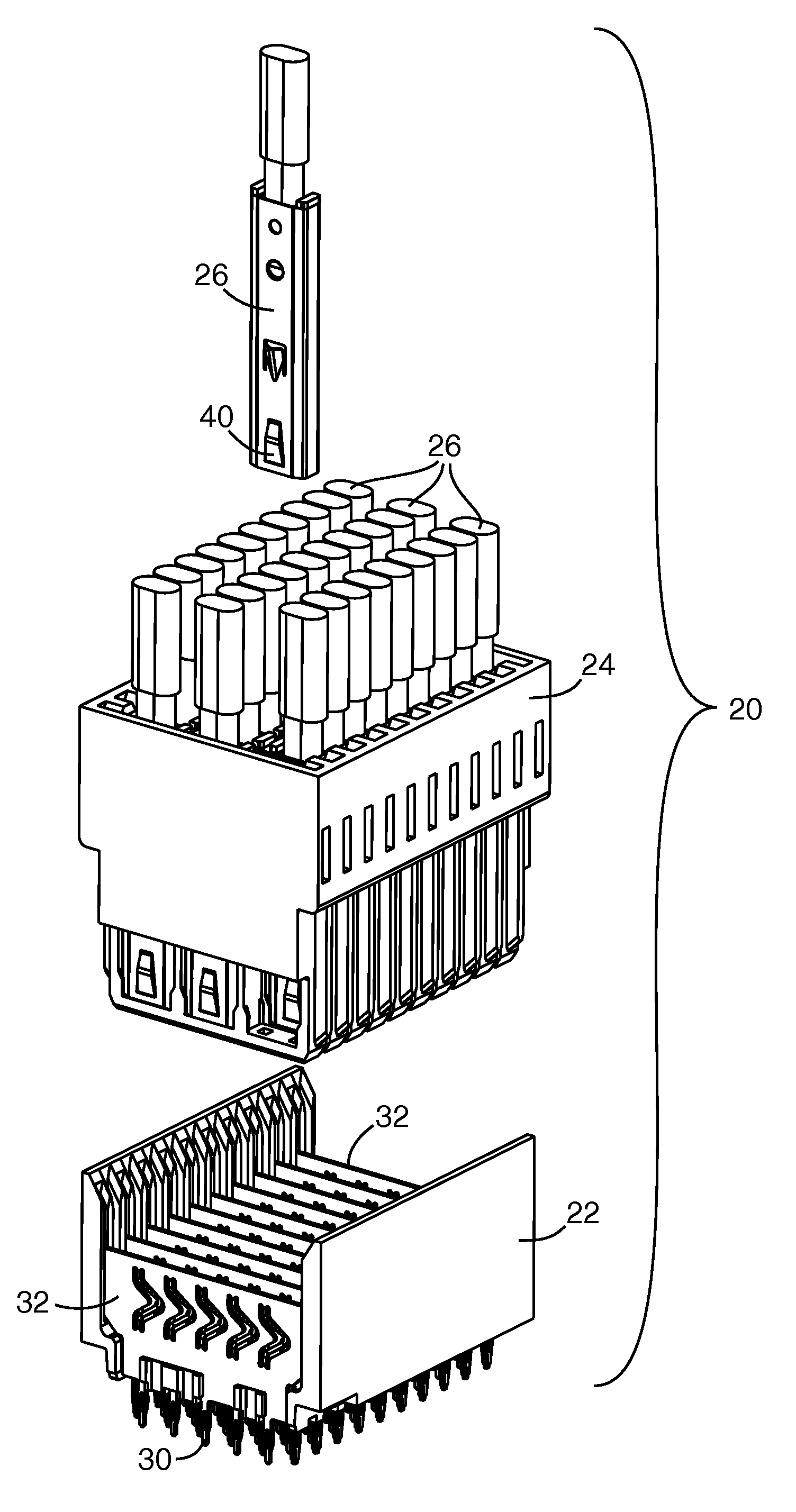
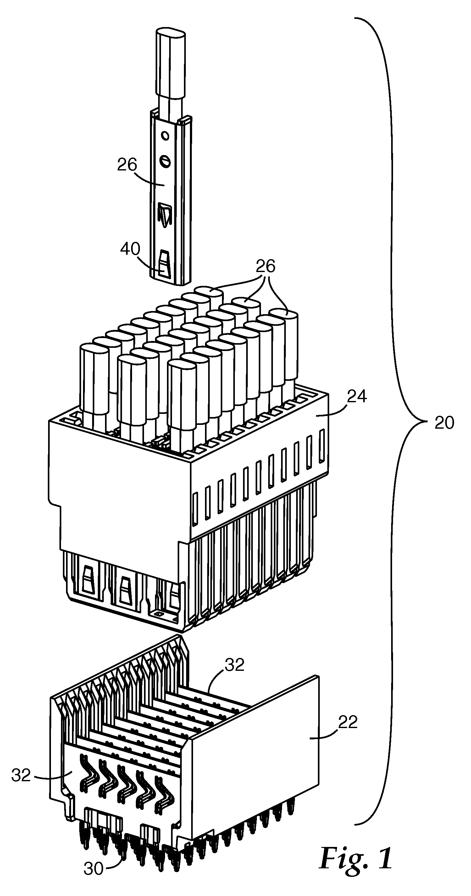
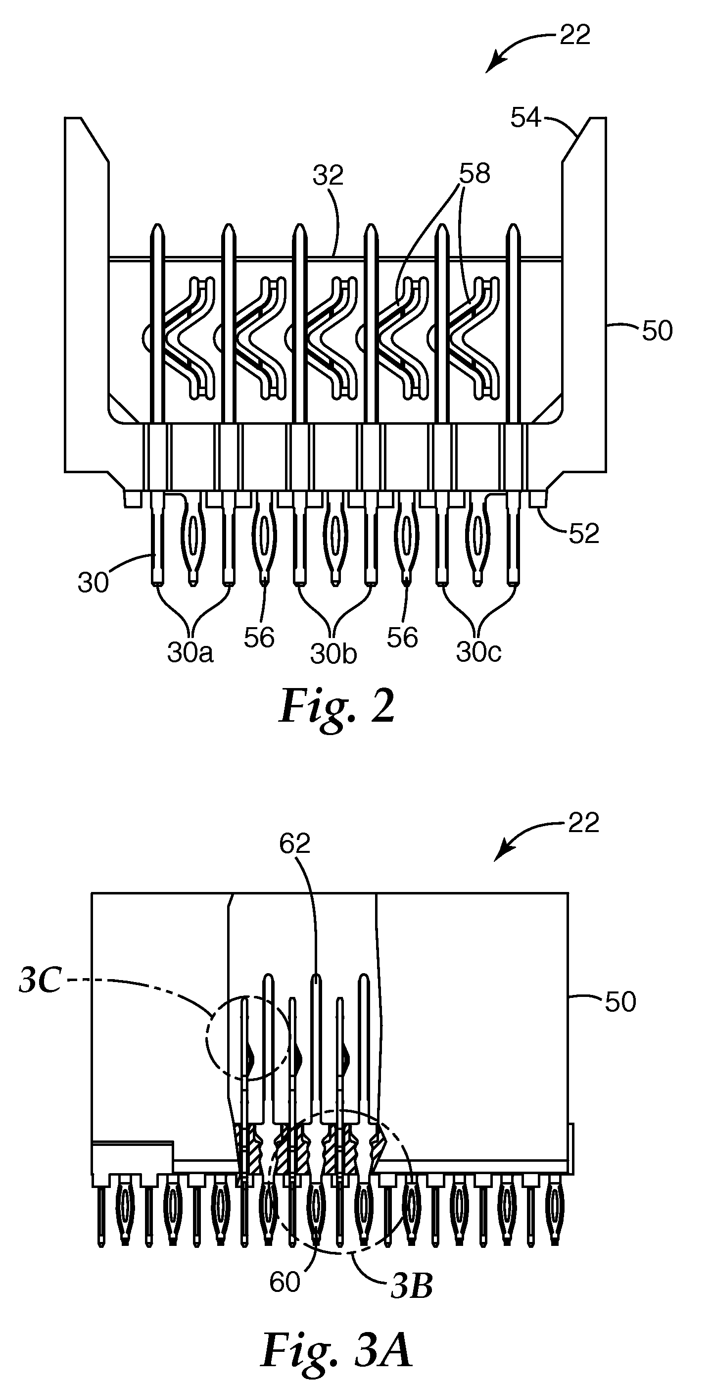
An electrical connector system includes a header and a carrier assembly attachable with the header. The header includes a leading end having a plurality of signal pins that are insertable into an electronic device and a stripline ground plate extending from the leading end toward a mating end. The carrier assembly is coupleable with the mating end of the header and includes a plurality of termination devices. Each termination device includes a cable terminated to a contact that electrically couples with one of the signal pins of the header, an insulator disposed around the contact, and a tubular shield disposed around the insulator. When the carrier assembly is connected to the header, the tubular shield contacts the stripline ground plate to commonly ground each signal pin/contact connection within the electrical connector system.

Description

BACKGROUND[0001]Headers are modular electrical connectors that provide signal paths for signals, such as differential signals, between a main board (e.g., a mother board) and a secondary board (e.g., a daughter board) or other electrical components.[0002]Headers are typically employed to electrically connect a large number of electrical signals between a series of daughter boards connected with a mother board in a manner that electrically interconnects different components in an electrical system. Other applications employ a header connected with a backplane or other connection board of an electronic system, where the header provides interconnection between the backplane and a carrier assembly attached to the header.[0003]The connectors attached to a printed circuit board or a backplane connect with conducting traces on the board / backplane, and the conducting traces connect to signal pins of the header to route the signals between conductors in the board / backplane (or electronic com...

Claims


Application Information

Patent Timeline
IPC IPC(8): H01R13/648
CPCH01R13/518H01R23/688H01R13/65802H01R13/6582H01R13/648H01R12/71
Inventor SCHERER, RICHARD J.CASTIGLIONE, JOSEPH N.JOSHI, ABHAY R.
Owner 3M INNOVATIVE PROPERTIES CO
Why Eureka
Try Eureka