
Electronic musical instrument with direct print interface

a printing interface and electronic musical technology, applied in the field of electronic musical instruments, can solve the problems of difficult to identify the setting state of electronic musical instruments at a glance, and it is not possible to view information displayed over a specific time period

Inactive Publication Date: 2010-06-29
YAMAHA CORP
View PDF32 Cites 14 Cited by
  • Summary
  • Abstract
  • Description
  • Claims
  • Application Information

AI Technical Summary

Benefits of technology

The present invention provides an electronic musical instrument that can easily print information about the instrument or music. It includes an input device for performance information, a tone generator, an operating panel with operators for setting the instrument's operating modes, and an interface for connecting to an external printer. The instrument has an image data generation part that creates print image data representing the contents of different scenes, which can be printed by the printer. The display device can switch between different scenes to show different music sounds and their settings. The image data generation part creates the print image data based on the positions and shapes of the display elements, and the display can display the print image data or a character or figure printed on the display. The instrument can also have a machine-readable medium for printing the music sounds and settings through an interface with an external printer. Overall, the invention provides an electronic musical instrument with a convenient and efficient way to print information about the instrument and music.

Problems solved by technology

However, in the technology of Japanese Patent Application Publication No. 2004-117487, information regarding the electronic musical instrument cannot be output through the printer without involving a personal computer.
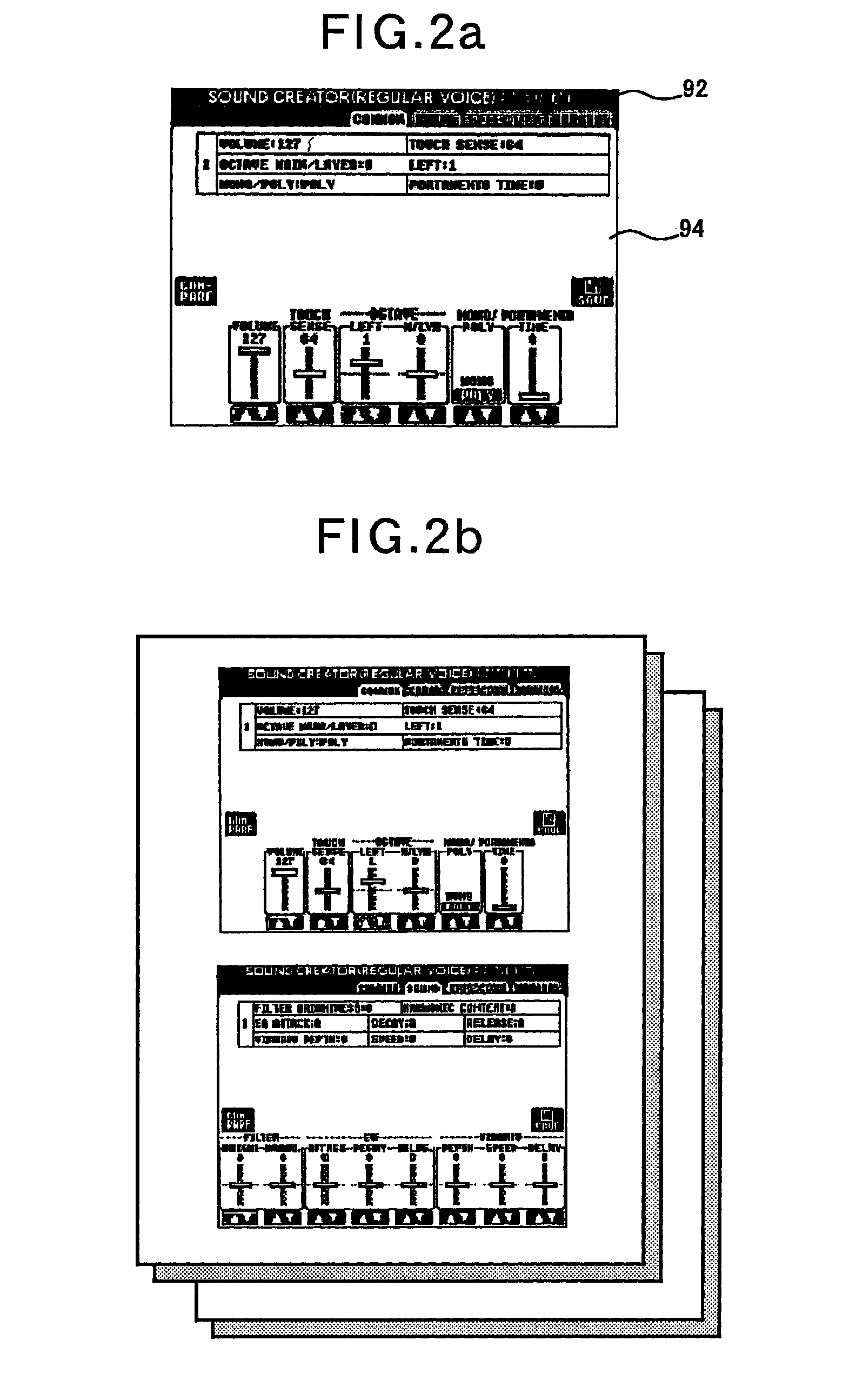
Thus, it is difficult to identify setting states of the electronic musical instrument at a glance and there is a demand for the capability to print a list of setting states so that the user can identify the setting states at a glance.
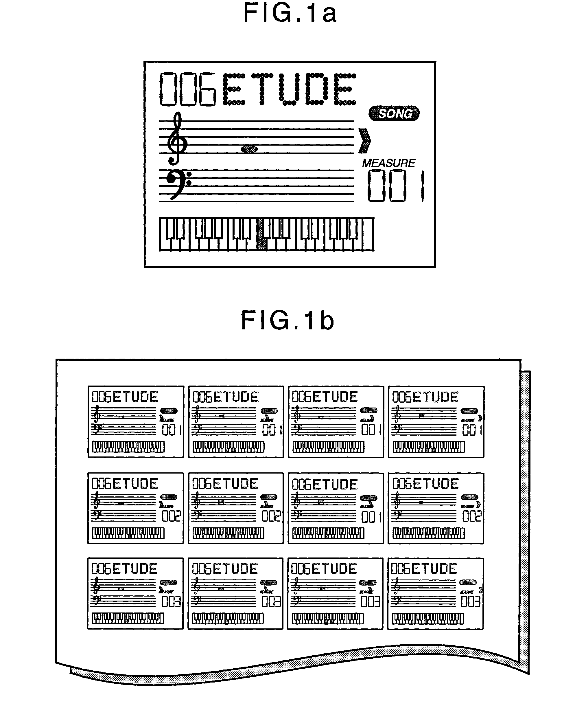
For example in case when a guide such as key positions for the song is displayed, since the displayed information is continuously switched as the song proceeds, it is not possible to view information displayed over a specific time period.
Recent electronic musical instruments have a high performance and require complex manipulations (or operations).
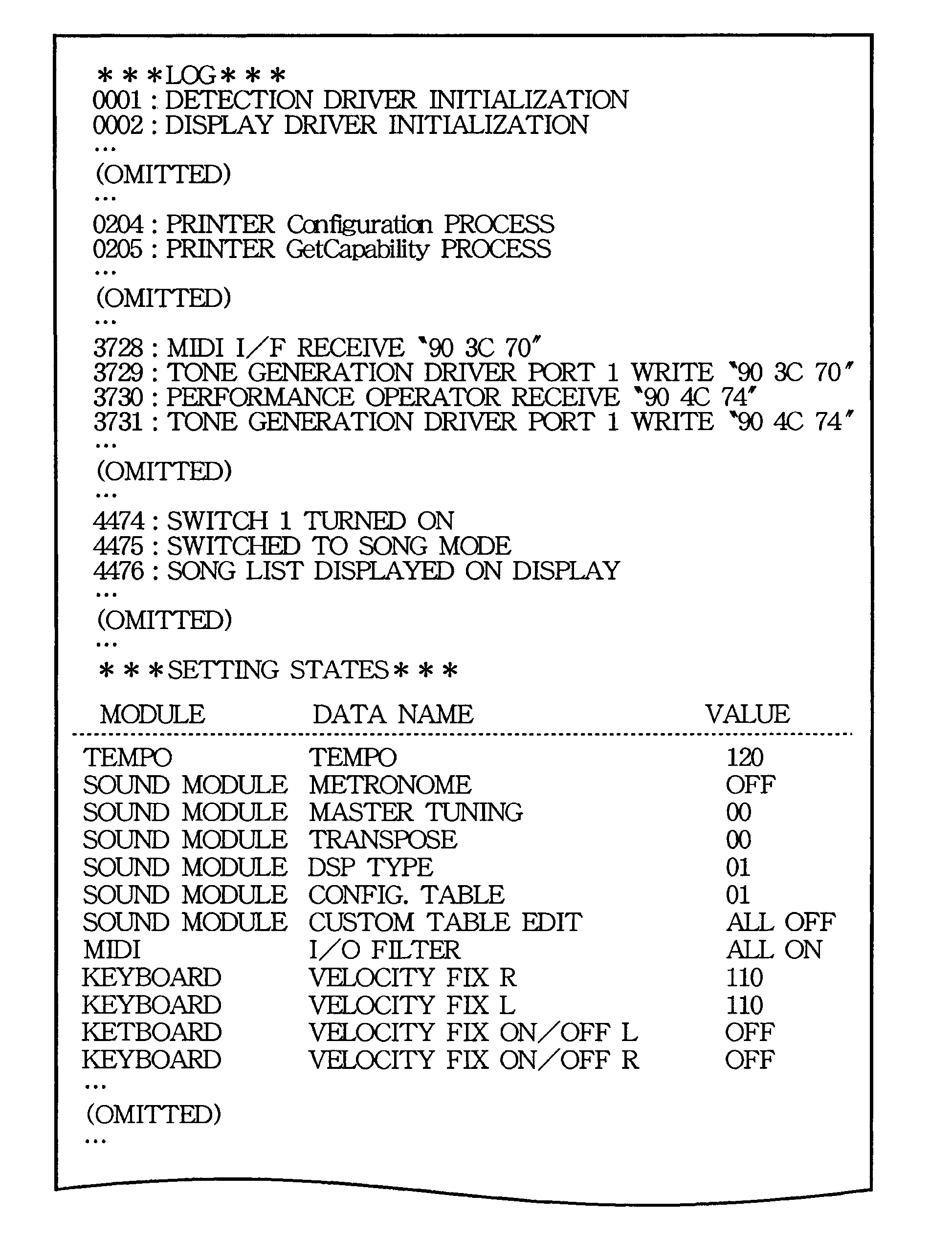
Thus, when the electronic musical instrument performs an unintended operation, the user cannot immediately determine whether the unintended operation is caused by an erroneous operation by the user or caused by a failure of the electronic musical instrument.
Especially, when the electronic musical instrument has no screen display function, it is difficult for the user to review setting states of its operating modes that have been set by using the operators.
Recent electronic musical instruments have a high performance and require complex manipulations (or operations).
Thus, when the electronic musical instrument performs an unintended operation, it is very difficult for the user to determine whether the unintended operation is caused by an erroneous operation by the user or caused by a software or hardware failure of the electronic musical instrument.
In addition, since the electronic musical instrument has a small display despite the complexity of its functions, it is difficult to display all states of the electronic musical instrument and it may also be difficult for the user to determine the states of the electronic musical instrument.

Method used


Image

  • Electronic musical instrument with direct print interface
  • Electronic musical instrument with direct print interface
  • Electronic musical instrument with direct print interface

Examples


first embodiment

2.3. Operation of First Embodiment

2.3.1. Overall Operation

[0081]The operation of the first embodiment will now be described. The USB interface 34 of the electronic musical instrument 100 and the printer 104 are connected through a USB cable. If both the electronic musical instrument 100 and the printer 104 are powered on, each detects the equipment type of each other (as a USB device or USB host). Each of the electronic musical instrument 100 and the printer 104 also detects that each other is PictBridge-enabled equipment. Then, the electronic musical instrument 100 detects that the printer 104 has a “print server function” of the PictBridge standard. In the following description, the electronic musical instrument 100 performs an operation for transmitting a variety of data to the printer 104 as needed based on an event generated at the electronic musical instrument 100. However, strictly speaking, communication between the electronic musical instrument 100 and the printer 104 is in...

second embodiment

3. Second Embodiment

3.1. Overall Configuration and Operation

[0109]The second embodiment will now be described. Although the second embodiment has a hardware structure similar to that of the first embodiment, a display including a dot matrix formed over its entirety is used instead of the display 10 of the first embodiment. In addition, although processes of the main routine of a print process of the second embodiment are also similar to those of the first embodiment (see FIG. 6), the main routine of the second embodiment is different from that of the first embodiment in that a print setting information creation subroutine shown in FIG. 10 is called at step SP4 and an image data file preparation subroutine shown in FIG. 11 is called at step SP8. Processes of these routines will now be described in detail.

3.2. Creation of Print Setting Information

[0110]At steps SP72 and SP74 of FIG. 10, a file format transmitted to the printer 104 and a print format are determined based on print capab...


PUM


Abstract

In an electronic musical instrument, an input device inputs performance information. A tone generator operates based on tone setting parameters for generating music sounds according to the performance information. A display is capable of switching a plurality of scenes for displaying either of the performance information or tone setting parameters. An image data generation part creates one or a plurality of print image data representing contents of the plurality of the scenes upon detecting a print instruction operation. An interface is provided in the electronic musical instrument to output the print image data directly to an external printer for printing out the contents of the scenes.

Description

BACKGROUND OF THE INVENTION[0001]1. Technical Field of the Invention[0002]The present invention relates to an electronic musical instrument which is connectable to a printer so that it can perform printing.[0003]Specifically, the present invention relates to an electronic musical instrument suitable for use in printing tone setting parameters, a performance guide image, and the like.[0004]Further, the present invention relates to an electronic musical instrument whose operating modes are set by a plurality of operators mounted on an operating panel.[0005]2. Description of the Related Art[0006]A conventional electronic musical instrument has a display for displaying a variety of information. For example, information such as tone parameters is displayed on the display. Japanese Patent Application Publication No. 2004-117487 has disclosed a technology in which an electronic musical instrument and a printer are connected to a personal computer so that electronic music score data on the ...

Claims


Application Information

Patent Timeline
Patent Type & Authority Patents(United States)
IPC IPC(8): G10H1/00
CPCG10H1/0008G10H2240/285G10H2220/015
Inventor FUKADA, ATSUSHIYAMAMOTO, SHUJI
Owner YAMAHA CORP
Learn More