

Imaging lens and image pickup apparatus
a technology of image pickup and image, which is applied in the direction of optics, instruments, optical elements, etc., can solve the problems of excessively reducing the size of the image, excessively increasing the number of pixels, and the lens is inappropriate for surveillance cameras or on-board cameras, and achieves good optical performance and small size.
- Summary
- Abstract
- Description
- Claims
- Application Information
AI Technical Summary
Benefits of technology
Problems solved by technology
Method used
Image

Examples
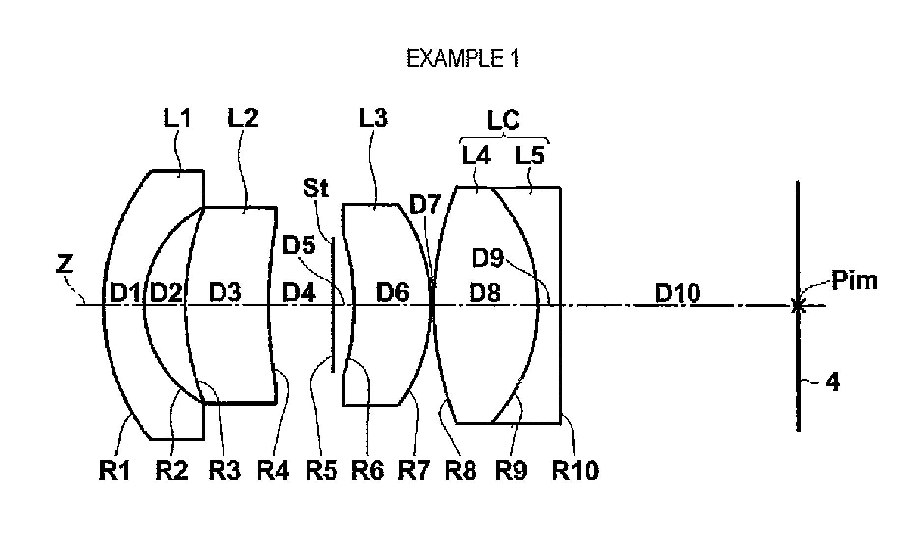
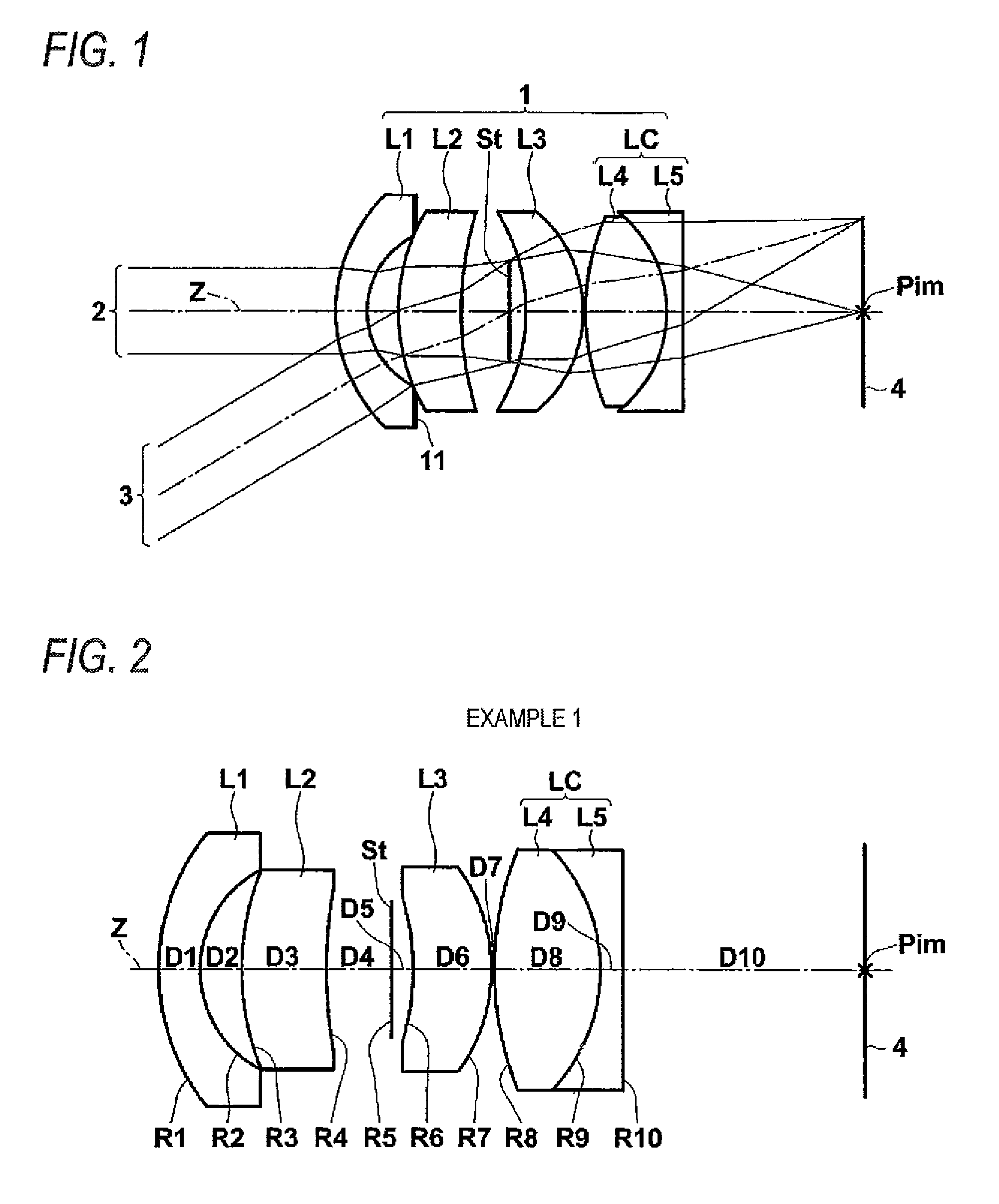
example 1
[0072]Table 1 shows lens data and various data of the imaging lens according to Example 1. In addition, in Table 1, various data is additionally shown in the lower part of the lens data. In the lens data of Table 1, a surface number represents the sequential number of i-th (i=1, 2, 3 . . . ) surface that sequentially increases as it gets closer to the image side when a surface of a component closest to the object side is defined as a first surface. In addition, in the lens data of Table 1, the aperture diaphragm St is also noted.
[0073]In Table 1, Ri represents a radius of curvature of i-th (i=1, 2, 3 . . . ) surface, and Di represents an on-axis surface spacing on the optical axis Z between the i-th (i=1, 2, 3 . . . ) surface and the (i+1)th surface on the optical. In addition, Ndj represents a refractive index with respect to d-line in a j-th (j=1, 2, 3 . . . ) optical element of which the sequential number sequentially increases as it gets closer to the image side when a surface o...
example 2
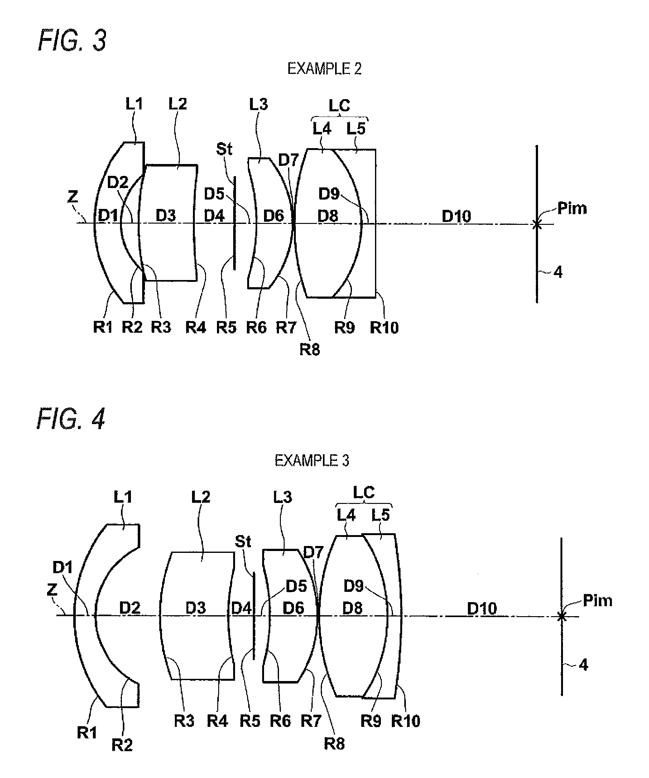
[0077]Table 2 shows lens data and various data of the imaging lens according to Example 2. FIG. 3 shows a lens configuration diagram. In FIG. 3, the reference signs Ri and Di correspond to the Ri and the Di in Table 2.
[0078]
TABLE 2Surface NumberRiDiNdjνdj 17.361.501.772549.6 23.711.02 313.573.261.755052.3 425.362.39 5(AD)∞1.28 6−10.832.101.834842.7 7−5.920.10 813.153.911.772549.6 9−6.300.811.846723.810∞9.4011(Image Plane)∞AD: Aperture DiaphragmFno. = 2.00, ω = 29.3, L = 25.8, f = 8.5, Bf = 9.40
example 3
[0079]Table 3 shows lens data and various data of the imaging lens according to Example 3. FIG. 4 shows a lens configuration diagram. In FIG. 4, the reference signs Ri and Di correspond to the Ri and the Di in Table 3.
[0080]
TABLE 3Surface NumberRiDiNdjνdj 18.591.201.772549.6 24.423.73 39.963.981.834842.7 411.311.50 5(AD)∞0.94 6−11.232.721.834842.7 7−7.100.10 811.244.011.713053.9 9−8.390.801.922918.910−29.339.3211(Image Plane)∞AD: Aperture DiaphragmFno. = 2.00, ω = 32.6, L = 28.3, f = 7.8, Bf = 9.32
PUM
 Abstract
Description
Claims
Application Information