Shield case

a shield case and shield technology, applied in the field of shield cases, can solve problems such as solder inspection, and achieve the effects of preventing the joint strength between the joint terminal and the circuit board surface from being decreased, increasing the joint strength, and reducing the resistance of solder

Inactive Publication Date: 2010-06-29
MURATA MFG CO LTD
View PDF19 Cites 9 Cited by
  • Summary
  • Abstract
  • Description
  • Claims
  • Application Information

AI Technical Summary

Benefits of technology

[0016]With this feature of the invention, the joint terminals of the shield case extend outward and are inclined upward from the lower edge of the shield case. For this reason, the distance between the joint terminals and the circuit board surface increases from the base ends of the joint terminals toward the leading ends. This increase allows more conductive joining material to be provided between the joint terminals and the circuit board surface than when the joint terminals extend along the circuit board surface. This easily increases the joint strength between the joint terminals of the shield case and the circuit board surface with the conductive joining material.
[0017]Since the distance between the leading ends of the joint terminals and the circuit board surface is longer than the distance between the base ends of the joint terminals and the circuit board surface, more joining material can be provided at the leading ends of the joint terminals than at the base ends. Therefore, even when fillets of the joining material are not formed at the leading ends of the joint terminals, a desirable joint strength can be ensured between the joint terminals and the circuit board surface. Accordingly, it is possible to prevent the joint strength between the joint terminals and the circuit board surface from being decreased when fillets are not easily formed at the leading ends of the joint terminals (for example, when leading end faces of the joint terminals are formed of a material that is not easily joined to the joining material, or the leading end faces are rough).
[0018]Further, with this feature of the invention, the joint terminals extending from the lower edge of the shield case can function as adjustable legs of the shield case. Therefore, when the joint terminals are inclined upward by being bent at the base ends, the shield case can be easily prevented from rattling when placed on the circuit board surface by adjusting the positions of the bent portions. This helps to avoid a defective joint terminal that is not joined to the circuit board surface because it is out of contact therewith. Thus, for example, it is unnecessary to perform a troublesome special operation for joining the shield case and the circuit board surface in a manner depending on the degree of rattling of the shield case with respect to the circuit board surface, so that the shield case can be properly joined more easily to the circuit board surface. Accordingly, the shield case with this feature is satisfactorily capable of automatic mounting, and achieves high mass productivity.
[0019]With the features described herein, it is easy to properly join the joint terminals of the shield case to the circuit board surface with the conductive joining material. Therefore, the entire shield case can be stably grounded to the ground portion of the circuit board via the joint portions between the joint terminals and the circuit board surface. This stabilizes the ground potential of the shield case, and enhances the reliability of shielding performance of the shield case.
[0020]Since the distance between the joint terminals and the circuit board surface increases from the base ends of the joint terminals toward the leading ends, the joining material provided between the joint terminals and the circuit board surface can be easily viewed from above the circuit board surface. For this reason, it is easy to visually check the state of the joint between the joint terminals and the circuit board surface with the joining material, and the operation efficiency during the checking process is enhanced.

Problems solved by technology

A third problem relates to inspection of the solder.

Method used


Image

  • Shield case
  • Shield case
  • Shield case

Examples


Embodiment Construction

[0045]Embodiments of the present invention will be described below with reference to the drawings.

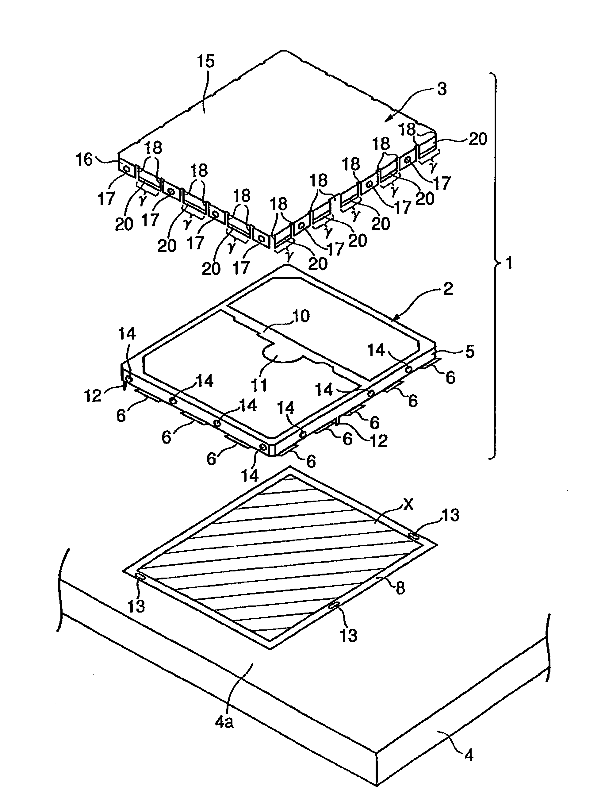
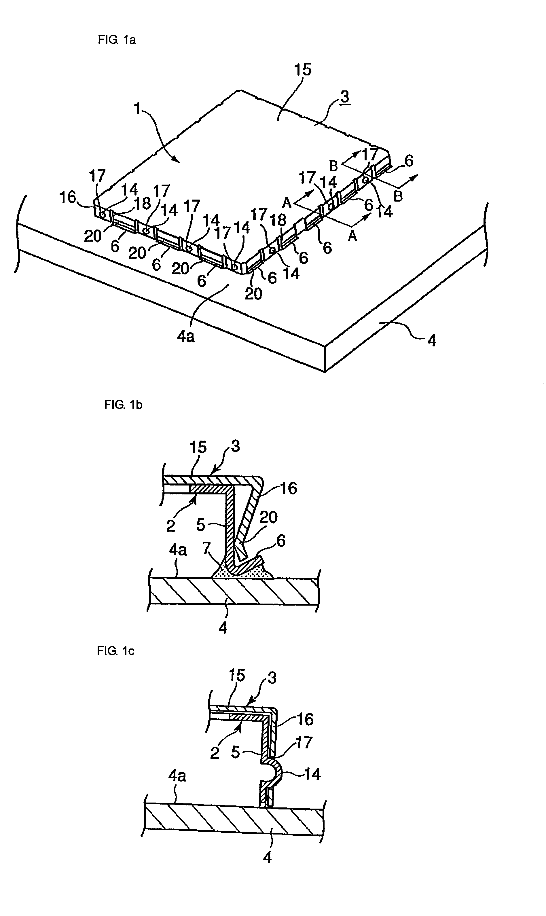
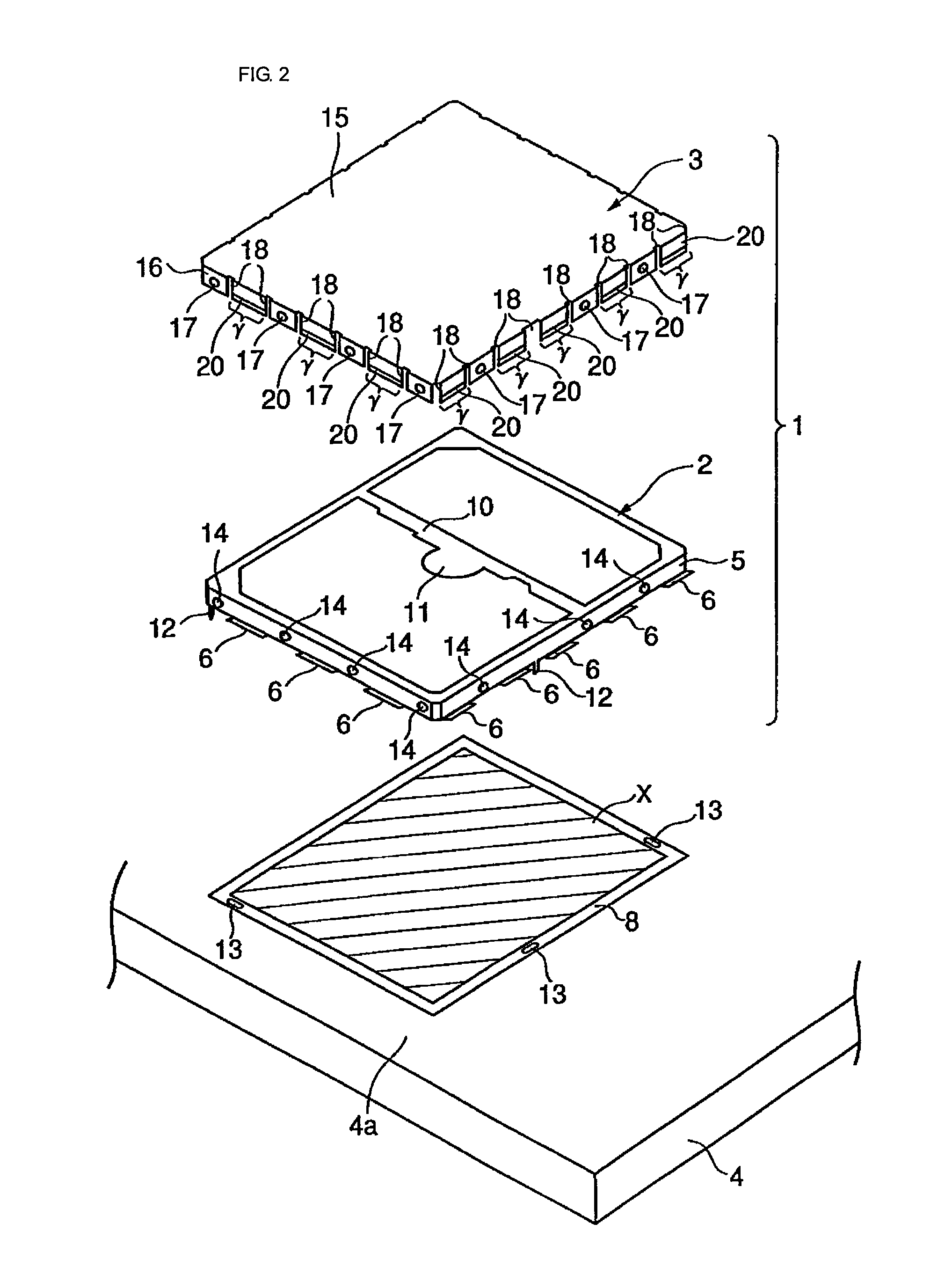
[0046]FIG. 1a is a schematic perspective view showing a shield case according to an embodiment of the present invention, along with a circuit board, FIG. 1b is a schematic cross-sectional view taken along line A-A in FIG. 1a, and FIG. 1c is a schematic cross-sectional view taken along line B-B in FIG. 1a. FIG. 2 schematically shows an exploded state of the shield case. A shield case 1 of this embodiment includes a frame 2 formed of a conductor and a cover 3 formed of a conductor that will be described below.

[0047]The frame 2 includes a peripheral wall 5 that surrounds a predetermined shielded portion (a diagonally shaded portion shown in FIG. 2) X on a surface 4a of a circuit board 4. The peripheral wall 5 has joint terminals 6 provided at a lower edge thereof so as to be in contact with the circuit board surface 4a. The joint terminals 6 extend outward from the lower edge of the periph...


PUM


Abstract

A shield case is fixed to a surface of a circuit board with a conductive joining material so as to cover a shielded portion on the circuit board surface. The shield case includes joint terminals extending outward and inclined upward from a lower edge thereof that is in contact with the circuit board surface. The joint terminals are joined to the circuit board surface with the conductive joining material provided therebetween. The shield case can thereby be fixed to the circuit board surface, and grounded to a ground portion provided on the circuit board.

Description

CROSS-REFERENCE TO RELATED APPLICATION[0001]The present application is a 35 U.S.C. §371 national phase conversion of PCT / JP2005 / 013394 filed on Jul. 21, 2005, which claims priority of Japanese Patent Appln. No. 2004-279752 filed Sep. 27, 2004 incorporated by reference.BACKGROUND OF THE INVENTION[0002]The present invention relates to a shield case that covers and shields a shield portion on a surface of a circuit board.BACKGROUND ART[0003]FIG. 5a is a schematic perspective view showing an example of a shield case along with a circuit board (for example, see Patent Document 1), and FIG. 5b illustrates an exploded state of the shield case shown in FIG. 5a. This shield case 40 covers and shields a shielded portion on a surface 41a of a circuit board 41. In this example, the shield case 40 includes a frame 42 formed of a conductor and a cover 43 formed of a conductor.[0004]The frame 42 is defined by a peripheral wall that surrounds the shielded portion on the circuit board surface 41a. T...

Claims


Application Information

Patent Timeline
Patent Type & Authority Patents(United States)
IPC IPC(8): H05K9/00
CPCH05K9/0032
Inventor KAKINOKI, WATARUNAKAZAWA, YUKIOHAYASHIKOSHI, KENJI
Owner MURATA MFG CO LTD
Why Eureka
Try Eureka