Component mounting apparatus and component mounting method

a technology for mounting apparatuses and components, applied in semiconductor/solid-state device testing/measurement, manufacturing tools, instruments, etc., to achieve the effect of reducing the stage, ensuring the stability of the mounting position, and efficient stacked mounting

Inactive Publication Date: 2010-07-06
PANASONIC CORP
View PDF11 Cites 6 Cited by
  • Summary
  • Abstract
  • Description
  • Claims
  • Application Information

AI Technical Summary

Benefits of technology

[0006]It is an object of the present invention to provide a component mounting apparatus and a component mounting method according to which the stacked mounting can be executed efficiently.
[0008]The mounting reference height calculation unit calculates the mounting reference height corresponding to the distance from the first reference height position to the substrate or the already mounted component, and then the first target movement height calculation unit calculates the first target movement height using the mounting reference height. The mounting head is moved downward from the first reference height position to the first target movement height, and the held component is mounted on the substrate or the already mounted component. Therefore, the greater the number of already mounted components, i.e. the greater the number of layers of the components already mounted on the substrate, the more the first target movement height is raised up to approach the first reference height position. In other words, as the number of layers of the components mounted on the substrate increases, the amount by which the mounting head holding the component to be mounted next is moved downward from the first reference height position toward the stage is automatically adjusted. As a result, a plurality of components can be stack-mounted continuously, thereby achieving efficient stacked mounting.
[0011]The component mounting may further comprise a recognition camera capable of recognizing at least the component held by the mounting head and the substrate, and the controller may execute alignment of the component held by the mounting head with the already mounted component using recognition result of the substrate by the recognition camera. Further, the component mounting apparatus may further comprising a recognition camera capable of recognizing at least the component held by the mounting head and a lowermost-layer component already mounted on the substrate, and the controller may execute alignment of the component held by the mounting head with the already mounted component using recognition result of the lowermost-layer component by the recognition camera. The aligning of the component to be mounted relative to the already mounted component always based on the same object, i.e. the substrate or the lowermost-layer component can achieve highly precise and stable stacked mounting. Furthermore, the component mounting apparatus may further comprise a recognition camera capable of recognizing at least the component held by the mounting head and an uppermost-layer component already mounted on the substrate, and the controller may execute alignment of the component held by the mounting head with the already mounted component using recognition result of the uppermost-layer component by the recognition camera.
[0020]According to the component mounting apparatus of the first aspect and the component mounting method of the third aspect of the present invention, as the number of already mounted components, i.e. the number of layers of components already mounted on the substrate, increases, the amount by which the mounting head which holds the component to be mounted next is moved downward toward the stage is automatically adjusted. As a result, a plurality of components can be stack-mounted continuously, and thus the stacked mounting can be executed efficiently.
[0021]According to the component mounting apparatus of the second aspect and the component mounting method of the fourth aspect of the present invention, the greater the number of already mounted components, i.e. the greater the number of layers of components already mounted on the substrate, the more the stage is lowered, thereby the mounting height position is automatically kept constant. As a result, a plurality of components can be stack-mounted continuously, and thus the stacked mounting can be executed efficiently. Further, because the mounting height is kept constant, the work distance between the component and a recognition camera disposed between the mounting head and the component is kept constant. As a result, the recognition camera can execute position recognition of the already mounted component with high precision, and thus more highly precise mounting on the already mounted component can be realized.

Problems solved by technology

However, a component mounting apparatus can execute the stacked mounting efficiently with consideration given to the characteristic of stacked mounting has not been provided.

Method used


Image

  • Component mounting apparatus and component mounting method
  • Component mounting apparatus and component mounting method
  • Component mounting apparatus and component mounting method

Examples


first embodiment

[0053]Next, embodiments of the present invention will be described in detail with reference to the attached drawings.

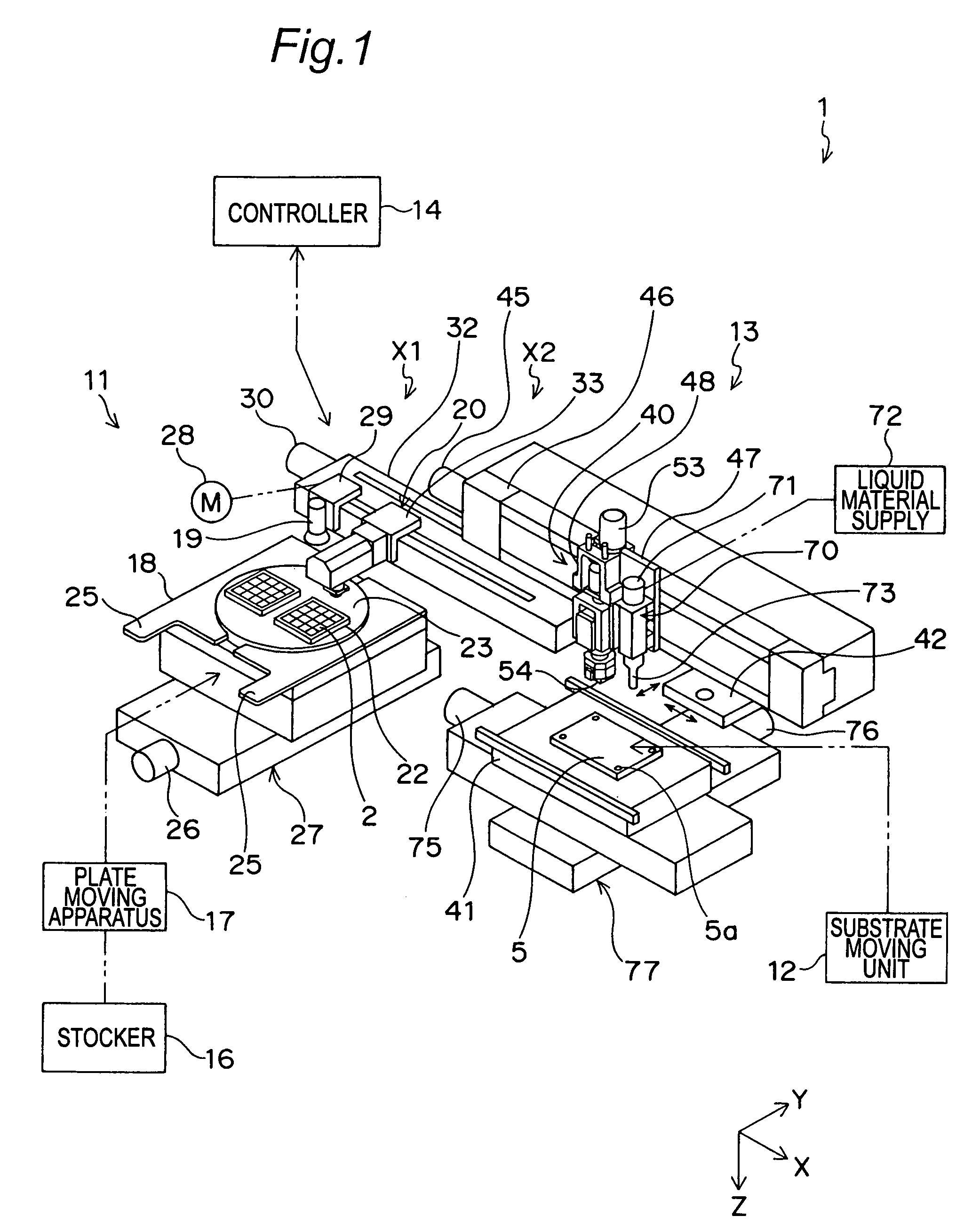
[0054]FIGS. 1 to 4 show a component mounting apparatus 1 according to a first embodiment of the present invention. This component mounting apparatus 1 is for carrying out or executing stacked mounting in which a plurality of IC chips (components) are mounted on a substrate in stack manner or so as to be stacked on each other. Referring to FIGS. 5A and 5B, each IC chip (chip) 2 has a plurality of pads (e.g. Au pads) 3 provided on one surface (a sucked surface) 2a thereof, and has a plurality of bumps (e.g. Au bumps) 4 provided on the other surface (a mounted surface) 2b thereof. FIG. 6 shows an example of a plurality of such chips 2 stack-mounted on a substrate 5. As shown in FIG. 6, the pads 3 are also provided on the substrate 5. A first layer chip 2-1 is mounted on the substrate 5, and a second layer chip 2-2 is mounted on the first layer chip 2-1. In the present ex...

second embodiment

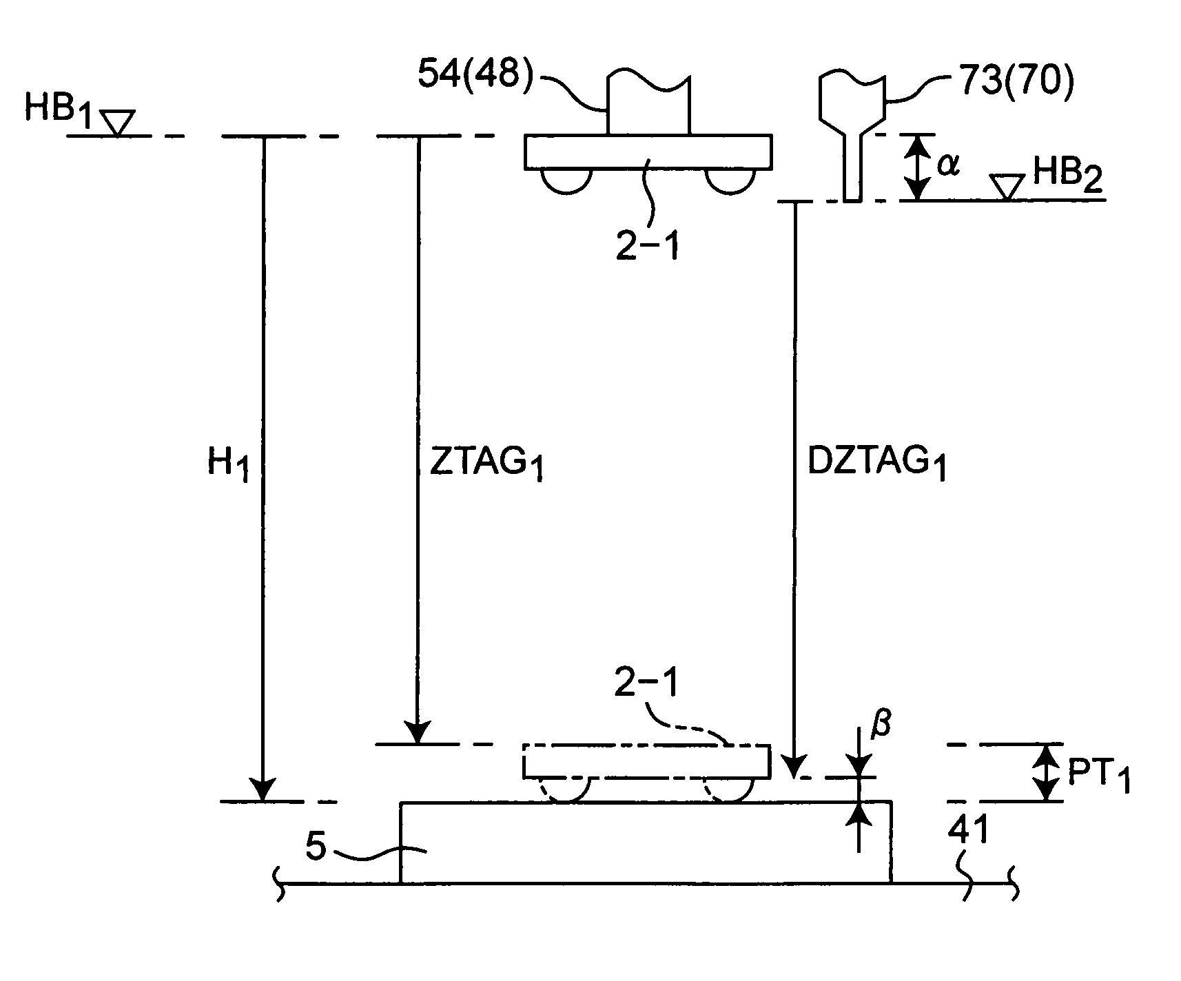
[0110]FIG. 9 shows the controller 14 in a second embodiment of the present invention. In the present embodiment, a set push in amount PHSETn for each stage is stored in the data storage unit 101. The set push in amount PHSETn is a set value for a distance by which the suction nozzle 54 is pushed into the nozzle supporting portion 56 vertically upward from the initial position PO1 (see FIG. 3) caused by that the mounting head 48 is further lowered after the chip 2 held by the suction nozzle 54 has contacted the substrate 5 or the already mounted chip when the mounting head 48 holding a chip 2 on the suction nozzle 54 is lowered from the first reference height position HB1 toward the substrate 5 or the already mounted chip 2. Further, the mounting reference height calculation unit 103 uses the set push in amount PHSETn and an actual push in amount PHACn, which is the actual measured value of the push in amount of the suction nozzle 54 as detected by the push in amount sensor 62, in th...

third embodiment

[0121]FIG. 12 shows the controller 14 in a third embodiment of the present invention. In the present embodiment, the mounting reference height calculation unit 103 uses an actual movement height ZACn in the calculation of the mounting reference height Hn. The actual movement height ZACn is the actual measured height of the mounting head 48 when mounting the chip 2 on the substrate 5 or the already mounted chip 2. This actual movement height ZACn is detected by the lowering amount sensor 61. Further, the basis for the actual movement height ZACn is the first reference height position HB1, with downward in the vertical direction being taken as positive.

[0122]The operation of the controller 14 and the mounting unit 13 will be described with reference to a flowchart of FIG. 13. Of steps S13-1 to S13-12, the processing at steps S13-1, S13-2, S13-4 to S13-9, S13-11 and S13-12 is the same as the processing in the corresponding steps in FIG. 7. In particular, at step S13-4, the first target...


PUM

PropertyMeasurementUnit
heightaaaaaaaaaa
distanceaaaaaaaaaa
thicknessaaaaaaaaaa

Abstract

A component mounting apparatus has a stage 41 with a fixed height position for holding a substrate 5, and a mounting head 48 that releasably holds a component 2, is moved downward toward the stage 41 from a first reference height position HB1 fixedly positioned above the stage 41, and mounts the held component 2 on the substrate 5 or an already mounted component 2. A controller 14 has a mounting reference height calculation unit 103 for calculating a mounting reference height Hn corresponding to a distance from the first reference height position HB1, and a first target movement height calculation unit 104 for calculating a first target movement height ZTAGn based on at least the mounting reference height Hn and a thickness PTn of the component 2 held by the mounting head 48. The controller 14 moves the mounting head 48 holding the component 2 downward from the first reference height position HB1 to the first target movement height ZTAGn to mount the held component 2 on the substrate 5 or the already mounted component 2.

Description

BACKGROUND OF THE INVENTION[0001]1. Technical Field of the Invention[0002]The present invention relates to a component mounting apparatus and a component mounting method. In particular, the present invention relates to an apparatus and method for stacked mounting in which a plurality of components such as IC chips are mounted on a substrate in stack manner.[0003]2. Description of Related Art[0004]Japanese Patent Application Laid-open Publication No. 2004-186182 discloses a component mounting apparatus for mounting IC chips on a substrate. This component mounting apparatus comprises a loader for supplying a substrate into the apparatus from outside the apparatus, a mounting stage for holding the substrate, a substrate carry-in apparatus for carrying the substrate from the loader onto the mounting stage, a mounting head for mounting IC chips onto the substrate held on the mounting stage, a conveying head for conveying the IC chips from a component supply unit to the mounting head, an ...

Claims


Application Information

Patent Timeline
Patent Type & Authority Patents(United States)
IPC IPC(8): H05K3/30
CPCH01L21/67253H01L21/67259H01L23/544H01L24/75H01L24/81H01L25/50H01L21/67144H01L21/563Y10T29/53187H01L2223/54426H01L2223/5448H01L2224/13144H01L2224/16H01L2224/75H01L2224/759H01L2224/81121H01L2224/81203H01L2224/81205H01L2224/81801H01L2225/06513H01L2924/01004H01L2924/01033H01L2924/01047H01L2924/01078H01L2924/01079H01L2924/01082H01L2924/14H01L2924/01005H01L2924/01006H01L2924/01084Y10T29/53183Y10T29/49131Y10T29/53174Y10T29/53178Y10T29/49133Y10T29/53039Y10T29/4913H01L2224/05573H01L2224/05568H01L2224/05644H01L2924/00014H01L2224/0554H01L2224/05599H01L2224/0555H01L2224/0556H05K13/02H05K13/04
Inventor HIRATA, SHUICHIMORIKAWA, MAKOTOMARUMO, SHINYAUENO, YASUHARUTSUJISAWA, TAKAFUMI
Owner PANASONIC CORP
Why Eureka
Try Eureka