Linear compressor

a compressor and linear technology, applied in the direction of positive displacement liquid engines, piston pumps, liquid fuel engines, etc., can solve the problems of increased stress to be applied to the suction valve, excessive opening of the suction valve, etc., to minimize the dead volume of the cylinder, reduce the degree of opening, and minimize the effect of stress

Inactive Publication Date: 2010-07-06
LG ELECTRONICS INC
View PDF24 Cites 10 Cited by
  • Summary
  • Abstract
  • Description
  • Claims
  • Application Information

AI Technical Summary

Benefits of technology

[0023]Therefore, the present invention has been made in view of the above problems, and it is an object of the present invention to provide a linear compressor including a suction valve stopper, which can limit the degree of opening of a suction valve when the suction valve 84 performs an opening operation, whereby there is no risk of deformation and damage to the suction valve due to the excessive opening of the suction valve, little vibration and noise are generated upon the opening / closing operations of the suction valve, and the compression efficiency of the linear compressor can be maintained at a constant value.
[0034]In the linear compressor according to the present invention, the suction valve is inserted in the piston to selectively connect the suction path of the piston to a compression chamber of the cylinder, and the suction valve stopper is provided to limit the degree of opening of the suction valve, whereby no excessive stress is applied to the suction valve. As a result, the linear compressor of the present invention has the effects of preventing deformation and damage to the suction valve, minimizing vibration and noise due to the opening / closing operations of the suction valve, and maintaining the compression efficiency of the compressor at a constant value.
[0036]Furthermore, the suction valve stopper of the present invention is configured to have a curved inner surface, such that the curved inner surfaces wholly comes into surface contact with the suction valve to limit the degree of opening of the suction valve, whereby more minimized stress is applied to the suction valve when the suction valve is opened, and the dead volume of the cylinder can be minimized.
[0037]The suction valve stopper is coupled to the piston to work in conjunction with the piston by use of a coupling member, which is also used to couple the suction valve to the piston. Thus, the suction valve stopper can achieve a simplified structure.
[0038]Also, the suction valve stopper is configured such that the coupling member is embedded in the suction valve stopper, resulting in a reduction in dead volume.

Problems solved by technology

A problem of the above-described conventional linear compressor is that the suction valve 22 may be excessively opened due to a large pressure difference between the suction path 21 of the piston 20 and the interior of the cylinder 10, as shown in FIG. 3.
This causes an increased stress to be applied to the suction valve 22, and therefore, there is a risk of plastic deformation or damage to the suction valve 22.
When the suction valve 22 exhibits such an excessively large degree of opening, an increased shock must be applied to the piston 20 when the suction valve 22 is closed, resulting in an increase in vibration and noise.
Therefore, an uneven amount of the working-fluid is sucked into the cylinder, making it impossible to achieve improved constant compression efficiency.
However, when working-fluid is nitrogen dioxide refrigerant, the working-fluid exhibits a relatively high working pressure, causing more severe stress to be applied to the suction valve 22.

Method used


Image

  • Linear compressor
  • Linear compressor
  • Linear compressor

Examples


Embodiment Construction

[0048]Now, a preferred embodiment of the present invention wall be explained with reference to the accompanying drawings.

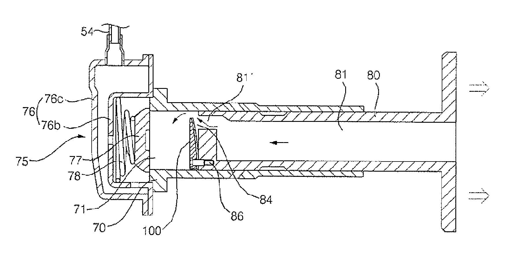
[0049]FIG. 4 is a sectional view illustrating a linear compressor according to the present invention. FIG. 5 is a view of important parts of the linear compressor according to the present invention, illustrating the advance movement of a piston. FIG. 6 is a sectional view taken along the line A-A of FIG. 5. FIG. 7 is a sectional view taken along the line B-B of FIG. 5. FIG. 8 is a view of important parts of the linear compressor according to the present invention, illustrating the retraction movement of the piston.

[0050]As shown in FIGS. 4 to 8, the linear compressor according to the present invention comprises a shell 50 configured to allow introduction and discharge of working fluid, a cylinder block 60 and a back cover 62 arranged in the shell 50, and a compression unit P provided between the cylinder block 60 and the back cover 62. The working-fluid, introduce...


PUM


Abstract

Disclosed herein is a linear compressor in which a piston reciprocally moves in a cylinder upon receiving a reciprocating drive force of a linear motor to compress working-fluid, for example, refrigerant, received in the cylinder. The linear compressor comprises the piston adapted to reciprocally move in the cylinder, the piston being internally formed with a suction path, a suction valve to open or close the suction path of the piston to selectively connect the suction path of the piston to the interior of the cylinder, and a suction valve stopper to limit the degree of opening of the suction valve, whereby no excessive stress is applied to the suction valve. This has the effect of eliminating damage and deformation of the suction valve, minimizing vibration and noise due to the opening / closing operations of the suction valve, and maintaining the compression efficiency of the compressor at a constant value.

Description

BACKGROUND OF THE INVENTION[0001]1. Field of the Invention[0002]The present invention relates to a linear compressor, and more particularly, to a linear compressor including a suction valve stopper, which limits the degree of opening of a suction valve when the suction valve performs an opening operation.[0003]2. Description of the Related Art[0004]Generally, a linear compressor is an apparatus configured in such a fashion that a piston reciprocates in a cylinder upon receiving a reciprocating drive force of a linear motor to compress working-fluid, for example, refrigerant, received in the cylinder. The linear compressor is mainly used in refrigerators, etc.[0005]FIG. 1 is a sectional view illustrating a conventional linear compressor. FIG. 2 is a view of important parts of the conventional linear compressor, illustrating the advance movement of a piston. FIG. 3 is a view of important parts of the conventional linear compressor, illustrating the retraction movement of the piston.[0...

Claims


Application Information

Patent Timeline
Patent Type & Authority Patents(United States)
IPC IPC(8): F04B39/10F04B53/12
CPCF04B35/045F04B39/0016Y10T137/7892
Inventor PARK, KYEONG BAECHOI, KI CHUL
Owner LG ELECTRONICS INC
Why Eureka
Try Eureka