Pulse fuel pump for a diaphragm carburetor

a diaphragm carburetor and fuel pump technology, which is applied in the direction of pump control, positive displacement liquid engine, charge feed system, etc., can solve the problems of increased output loss, increased exhaust conditions, and increased fuel retention in constant fuel chambers, so as to reduce the degree of opening of the control valve, the effect of increasing the quantity of fuel retained in the constant fuel chamber and enhancing the fuel flow to the suction channel

Active Publication Date: 2006-12-05
ZAMA JAPAN
View PDF3 Cites 0 Cited by
  • Summary
  • Abstract
  • Description
  • Claims
  • Application Information

AI Technical Summary

Benefits of technology

[0014]The present invention provides a solution to the above-described drawbacks in a conventional delivery fuel pressure adjusting means composed of a throttle or a throttle valve in the escape channel in which variability in the fuel flow rate due to variation in the constituent components of the carburetor cannot be corrected to meet emission regulations. An object thereof is to provide a pulse-type diaphragm fuel pump comprising a delivery fuel pressure adjusting means that is capable of arbitrarily adjusting the delivery fuel pressure exerted on the fuel valve so as to solve the variability of the fuel flow rate created by variation in the constituent components of the carburetor, making it possible to set the fuel flow rate supplied to the engine to an accurate flow that meets emission regulations, and hence to allow the engine to operate in a stable manner.
[0016]When the fuel flow rate changes to one that is less than a predetermined quantity due to the variation in constituent components of carburetors, the quantity of fuel retained in the constant fuel chamber can be increased and the fuel flow rate to the suction channel enhanced by decreasing the degree of opening of the control valve to reduce the fuel escape quantity, increase the pressure exerted on the fuel valve, and facilitate opening. When the fuel flow rate conversely changes to one that is greater than a predetermined quantity, the quantity of fuel retained in the constant fuel chamber can be decreased and the fuel flow rate to the suction channel enhanced by increasing the degree of opening of the control valve to increase the fuel escape quantity, reduce the pressure exerted on the fuel valve, and impede opening.
[0017]In other words, by adjusting the degree of opening of the control valve, the delivery fuel pressure exerted on the fuel valve can be steplessly changed, variability of the fuel flow rate due to variation in the constituent components of a carburetor can be corrected, and a predetermined flow rate of fuel can be accurately supplied, with the result that the objective of meeting emission regulations and consequently making the operability of the engine stable can be achieved.
[0018]In a carburetor wherein a throttle, in addition to a control valve, is provided to the escape channel, the delivery fuel pressure exerted on the fuel valve does not reach or fall below a fixed value even if the control valve is completely opened, and the minimum fuel flow rate required by the engine can be held to a range which allows the objectives of the present invention to be achieved.

Problems solved by technology

In a range of high speed rotation, drawbacks are demonstrated in that the delivery fuel pressure becomes greater than the specified pressure that works on the fuel valve.
As a result, the valve is forcefully opened, fuel from the constant fuel chamber is supplied in excess, and the air-fuel mixture is made rich, causing output to be lost and exhaust conditions to be worsened.
In common practice, there are variations in all components of a carburetor that cannot be avoided in the production process.
In particular, variations in the components related to the fuel flow rate and disposed in the fuel passage that reaches the suction channel from the constant fuel chamber varies the fuel flow rate supplied to the engine and directly affects the exhaust condition.
As a result, variability in the fuel flow rate created by variation in the constituent components of the fuel passage, which reaches the suction channel from the constant fuel chambers 61 and 81, cannot be corrected, and it is impossible to precisely control the fuel flow rate so as to meet emission regulations.

Method used


Image

  • Pulse fuel pump for a diaphragm carburetor
  • Pulse fuel pump for a diaphragm carburetor
  • Pulse fuel pump for a diaphragm carburetor

Examples


Embodiment Construction

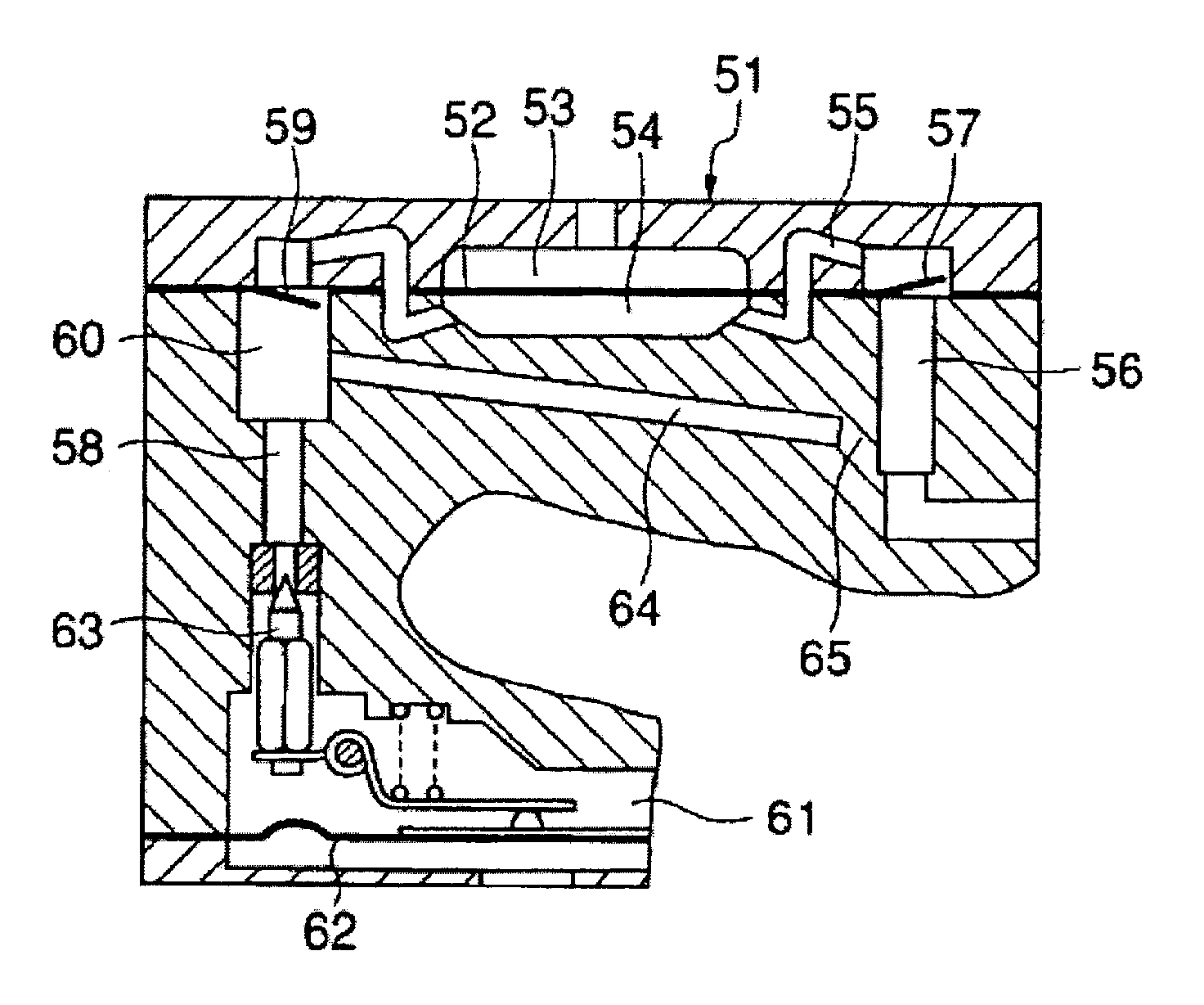
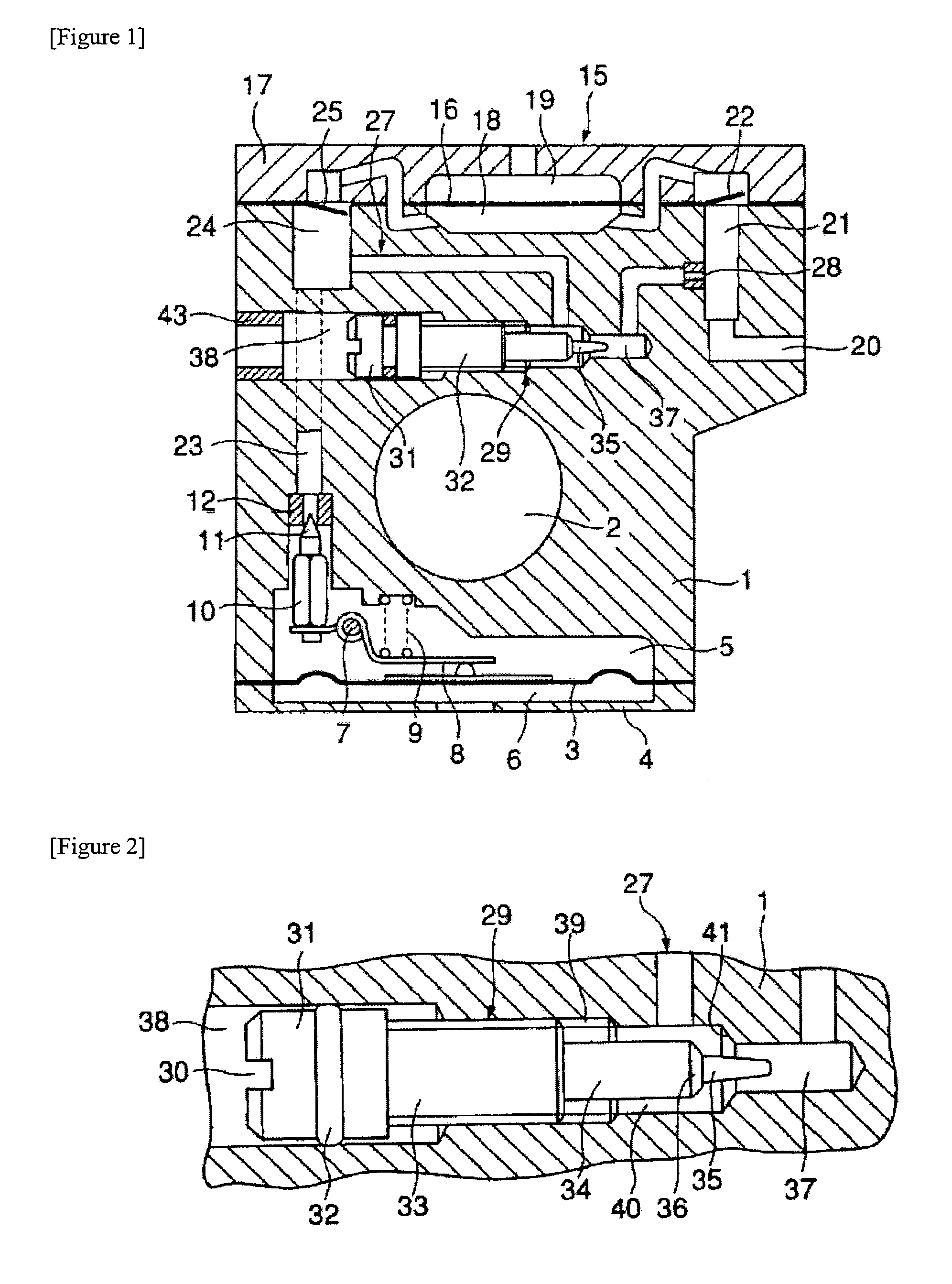
[0023]FIGS. 1 and 2 show an embodiment in which the present invention is integrally incorporated into a diaphragm-type carburetor. A diaphragm 3 and a diaphragm cover 4 are overlaid on the lower surface of a main body 1. A suction channel 2 having a venturi tube and throttle valve is laterally formed completely through the main body 1. The internal space of a diaphragm cover 4 and the cavity of the main body 1 facing each other across a diaphragm 3 form a constant fuel chamber 5 and a back pressure chamber 6 connected to the atmosphere.

[0024]A lever 8 supported in a freely rotatable manner by a pin 7 is mounted inside the constant fuel chamber 5. One end of this lever 8 is held in constant contact with the center portion of the diaphragm 3 by a spring 9, and the fuel valve 10 is attached to the other end. The valve element 11 of the fuel valve 10 is needle-shaped or conically shaped, and is seated in a valve seat 12, which is disposed on the exit end of the constant fuel chamber 5 o...


PUM


Abstract

A device that corrects with ease and high precision any deviation of the fuel flow rate due to variation in the constituent components of a carburetor, and to improve the exhaust condition and operability of an engine. A carburetor in which the delivery channel 23 and the suction channel 20 of a fuel pump 15 are connected with the aid of an escape channel 27, and in which a portion of the delivery fuel is allowed to escape to the suction side in order to prevent pressure exerted on the fuel valve 10 by the fuel delivered to the constant fuel chamber 5 from the fuel pump 15, which operates by pressure pulses, from reaching or exceeding a specified level, wherein the escape channel 27 is equipped with a manual control valve 29 for steplessly adjusting the surface area thereof. The quantity of fuel retained in the constant fuel chamber 5 can be adjusted so as to achieve a predetermined fuel flow rate by changing the escape quantity of the delivery fuel and rendering the fuel valve 10 more resistant to opening or less resistant to opening.

Description

FIELD OF THE INVENTION[0001]The present invention relates to pulse-type diaphragm fuel pump for suppying fuel from a fuel tank to a diaphragm-type or float-type constant fuel chamber of a carburetor.[0002]There are pulse-type diaphragm fuel pumps in which the diaphragm performs reciprocating displacement motion by pressure pulses generated in the suction manifold or the crankcase in association with the rotation of the engine, commonly by pressure pulses generated in the crankcase, which operate to suction fuel from the fuel tank into the pump chamber at negative pressure, and to deliver fuel from the pump chamber toward the constant fuel chamber of a carburetor at positive pressure. These pumps are widely used as means to supply fuel to the carburetor, which supplies fuel to general-purpose engines.[0003]The fuel valve, which allows or stops the flow of fuel delivered from the fuel pump into the constant fuel chamber, opens and closes so as to retain a fixed quantity of fuel in the...

Claims


Application Information

Patent Timeline
Patent Type & Authority Patents(United States)
IPC IPC(8): F04B23/00F04B49/00F02M17/04F02M19/06F04B43/06
CPCF02M17/04F04B43/06
Inventor NONAKA, TAKUMI
Owner ZAMA JAPAN
Why Eureka
Try Eureka