Variable valve

a variable valve and valve body technology, applied in the field of variable valves, can solve the problems of interference with peripheral components, abnormal noise, and inability to precisely control the flow rate, and achieve the effect of efficient control of the flow ra

Active Publication Date: 2017-10-10
HYUNDAI MOTOR CO LTD
View PDF11 Cites 0 Cited by
  • Summary
  • Abstract
  • Description
  • Claims
  • Application Information

AI Technical Summary

Benefits of technology

[0018]Various aspects of the present invention are directed to providing a variable valve, in which a flat spring is used to inhibit the occurrence of abnormal noise and more precisely control a flow rate, and two gates are independently opened and closed in order to more efficiently control a flow rate of exhaust gas in accordance with traveling situations of the vehicle under an actual vehicle condition.
[0022]The first spring and the second spring may each be a flat spring bent in a ‘C’ shape, and having a bent portion that is additionally bent at an upper end of the flat spring so as to prevent excessive elastic deformation.
[0024]According to the present invention having the aforementioned configurations, the first gate and the second gate independently control a flow rate of exhaust gas in accordance with the situations, that is, when the vehicle is idling and a relatively small amount of exhaust gas is produced and when the vehicle travels and a relatively large amount of exhaust gas is produced, thereby maximizing NVH performance and power performance of the vehicle.
[0025]The first gate and the second gate are coupled to flat springs having a ‘C’ shape, thereby improving durability in comparison with the coil-shaped torsion spring in the related art. The bent portion is formed at the end of the flat spring, thereby preventing the flat spring from being excessively deformed elastically and restricting opening degrees of the first gate and the second gate.

Problems solved by technology

However, when the variable valve in the related art is used under an environment having a predetermined high temperature, spring properties of the torsion spring 3 significantly deteriorate and thus it is impossible to precisely control a flow rate, and as a result, there is a problem in that when the gate 2 is opened up to a designed value or larger, interference with peripheral components occurs.
In the case of the variable valve in the related art, one end of the torsion spring 3 is just in point contact with the gate 2 to support the gate 2, and as a result, there are problems in that abnormal noise occurs due to rattling of the gate 2 because the torsion spring 3 does not durably support the motion of the gate 2, and abnormal touching noise occurs due to a collision between the gate 2 and the housing 1 when the gate 2 is closed.
That is, in a situation in which flow conditions of exhaust gas vary, it is difficult to cope with noise, vibration and harshness (NVH) performance of the vehicle and efficiently control an opening degree of the gate 2 by using only the single torsion spring 3 like the structure in the related art.

Method used


Image

  • Variable valve
  • Variable valve
  • Variable valve

Examples


Embodiment Construction

[0036]Reference will now be made in detail to various embodiments of the present invention(s), examples of which are illustrated in the accompanying drawings and described below. While the inventions) will be described in conjunction with exemplary embodiments, it will be understood that the present description is not intended to limit the invention(s) to those exemplary embodiments. On the contrary, the invention(s) is / are intended to cover not only the exemplary embodiments, but also various alternatives, modifications, equivalents and other embodiments, which may be included within the spirit and scope of the invention as defined by the appended claims.

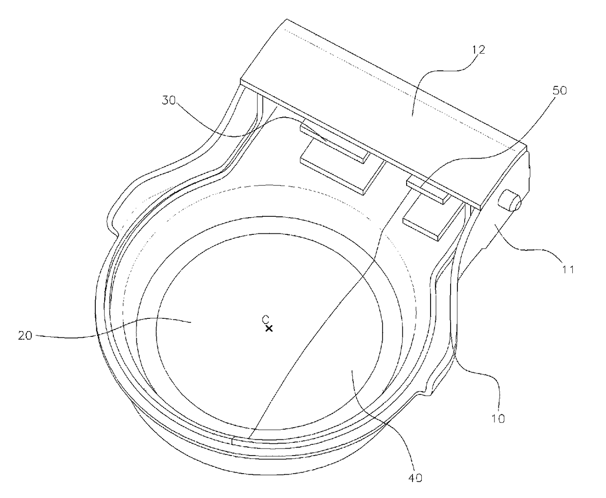
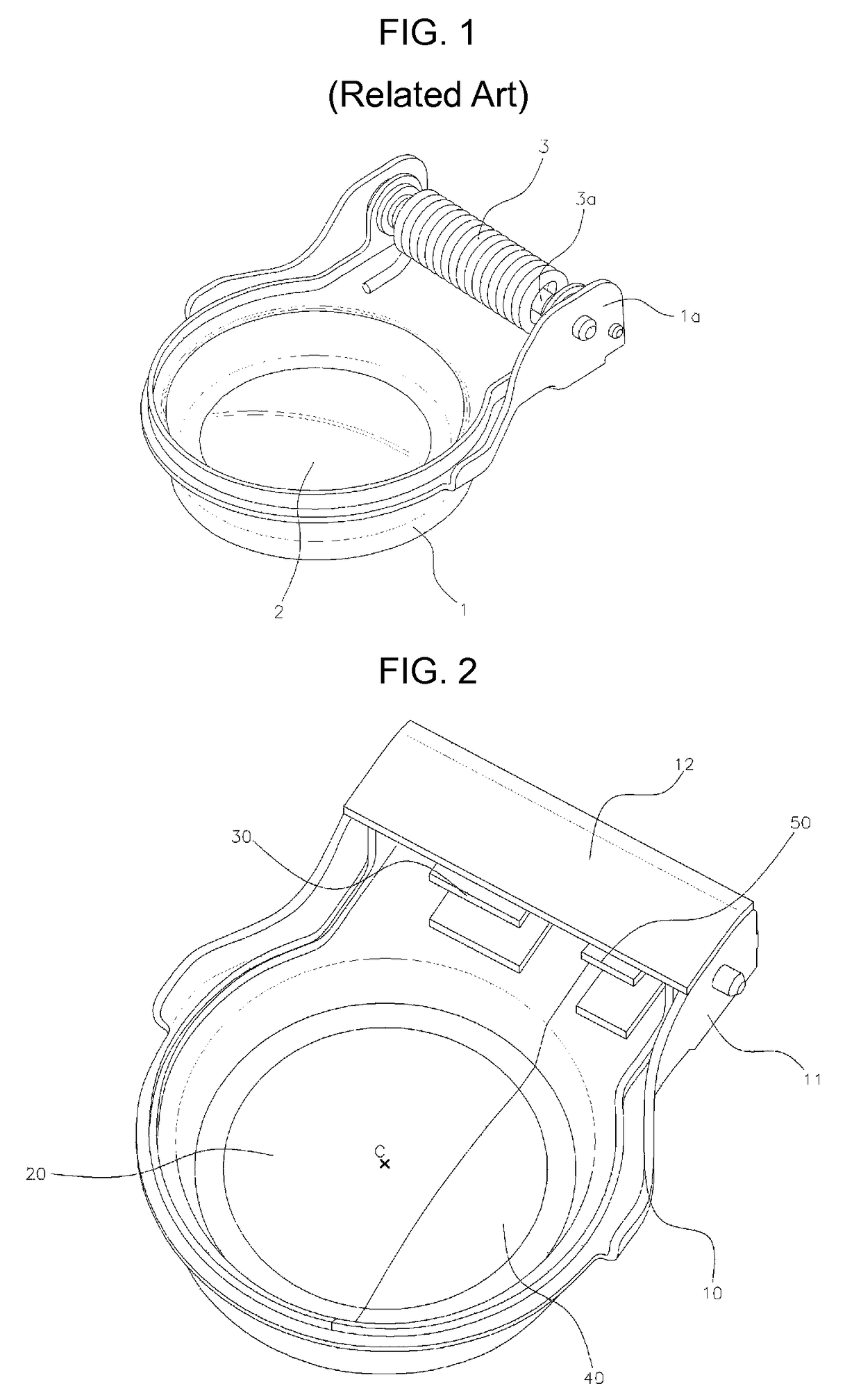
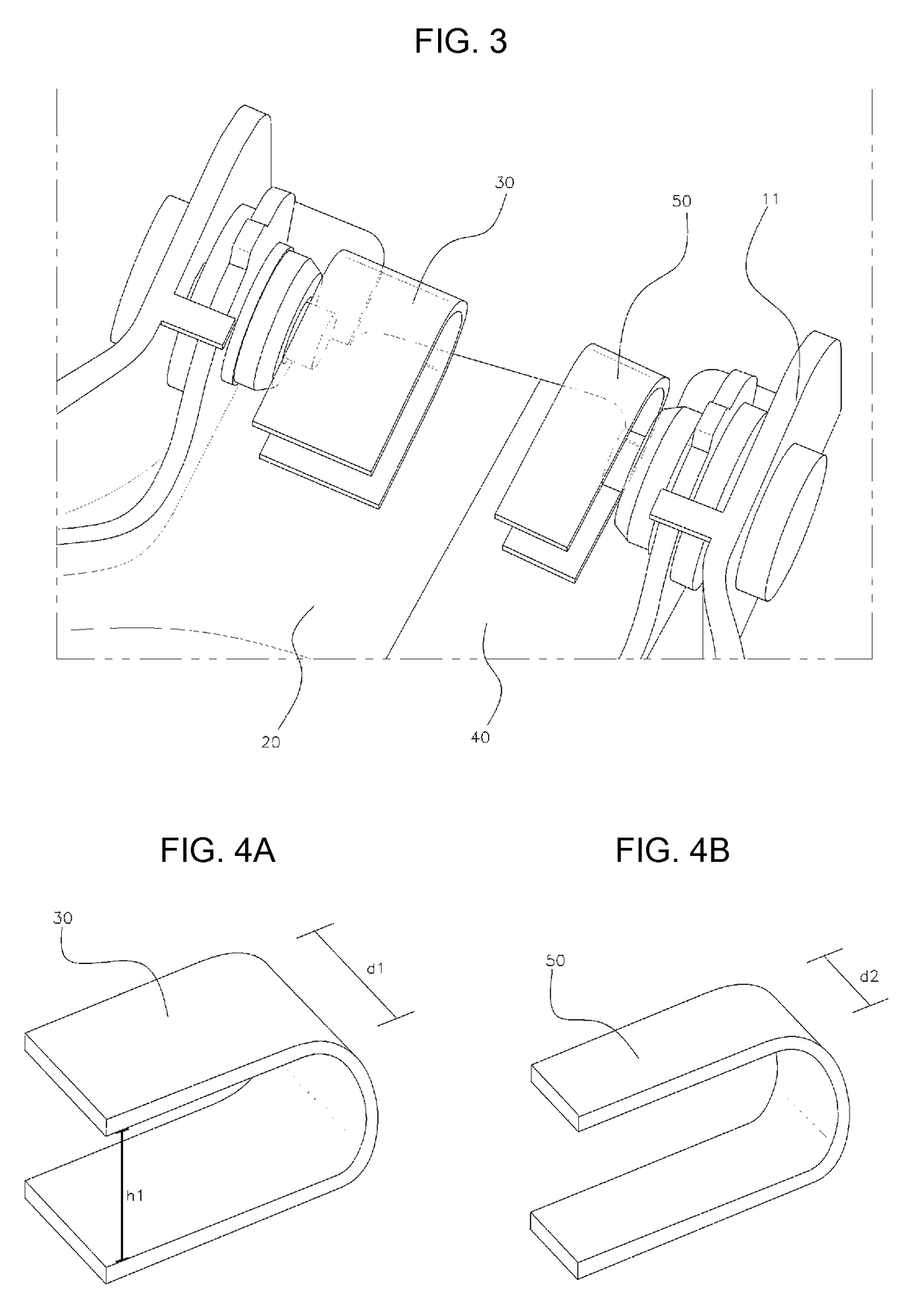
[0037]Referring to FIG. 2 and FIG. 3, a variable valve according to the present invention has a structure in which a first gate 20 and a second gate 40 are independently rotatably coupled to a housing 10.

[0038]Hinge support portions 11 protrude from one side of the housing 10, and an opening (see FIG. 6 and FIG. 7) through which ex...


PUM


Abstract

A variable valve may include a housing having hinge support portions protruding from a first side thereof, and an opening at a second side thereof, a first gate rotatably coupled to the hinge support portions so as to open and close a part of the opening, a first spring mounted on the housing to apply elastic force in a direction in which the first gate is closed, a second gate rotatably coupled to the hinge support portions so as to open and close a remaining part of the opening, and a second spring mounted on the housing to apply elastic force in a direction in which the second gate is closed, in which the first spring and the second spring may have different spring constants.

Description

CROSS-REFERENCE TO RELATED APPLICATION[0001]The present application claims priority to Korean Patent Application No. 10-2015-0063137, filed May 6, 2015, the entire contents of which is incorporated herein for all purposes by this reference.BACKGROUND OF THE INVENTION[0002]Field of the Invention[0003]The present invention relates to a variable valve that is adjusted to be opened and closed by flow pressure of exhaust gas, and more particularly, to a variable valve in which two gates open and close an opening, and springs connected with the gates are set to have different spring properties to allow the variable valve to be partially opened.[0004]Description of Related Art[0005]An exhaust system, which discharges exhaust gas produced in an engine to a rear side of a vehicle body, includes a muffler that reduces exhaust noise when exhaust gas is discharged.[0006]The muffler mounted in a vehicle is formed in a cylindrical shape having a predetermined shape, and a plurality of pipes and b...

Claims


Application Information

Patent Timeline
Patent Type & Authority Patents(United States)
IPC IPC(8): F01N1/16F16K15/03
CPCF01N1/163F01N1/165F01N1/166F16K15/033F16K15/035F01N1/168F01N2390/08F01N2260/14
Inventor YANG, YOUNG-DUG
Owner HYUNDAI MOTOR CO LTD
Why Eureka
Try Eureka