
System and method for testing a clock circuit

Active Publication Date: 2010-07-06
INTEGRATED DEVICE TECH INC
View PDF11 Cites 36 Cited by
  • Summary
  • Abstract
  • Description
  • Claims
  • Application Information

AI Technical Summary

Benefits of technology

[0010]Because the tolerance of the elevated frequency is higher than the tolerance of the specified frequency, the first counter and the second counter each require fewer bits than a counter that counts clock cycles within the tolerance of the specified frequency. Moreover, the test interval for counting clock cycles within the tolerance of the elevated frequency is shorter than a test interval for counting clock cycles within the tolerance of the specified frequency, which reduces test time for testing the clock circuit.
[0011]In a further embodiment, determining whether the frequency of the input clock signal is above the input threshold frequency is performed to determine whether the frequency of the feedback clock signal is locked to the frequency of the input clock signal. If the frequency of the feedback clock signal is not above the input threshold frequency, the frequency of the feedback clock signal is determined not to be locked to the frequency of the input clock signal. In this way, test time for determining whether the frequency of the feedback clock signal is locked to the frequency of the input clock signal is reduced.

Problems solved by technology

Additionally, the delay-locked loop circuit delays the input clock signal by one or more clock periods to generate the output clock signal.
Increasing the test interval, however, consumes valuable test time in testing the integrated circuit.
Moreover, the test interval for counting clock cycles within the tolerance of the elevated frequency is shorter than a test interval for counting clock cycles within the tolerance of the specified frequency, which reduces test time for testing the clock circuit.

Method used


Image

  • System and method for testing a clock circuit
  • System and method for testing a clock circuit
  • System and method for testing a clock circuit

Examples


Embodiment Construction

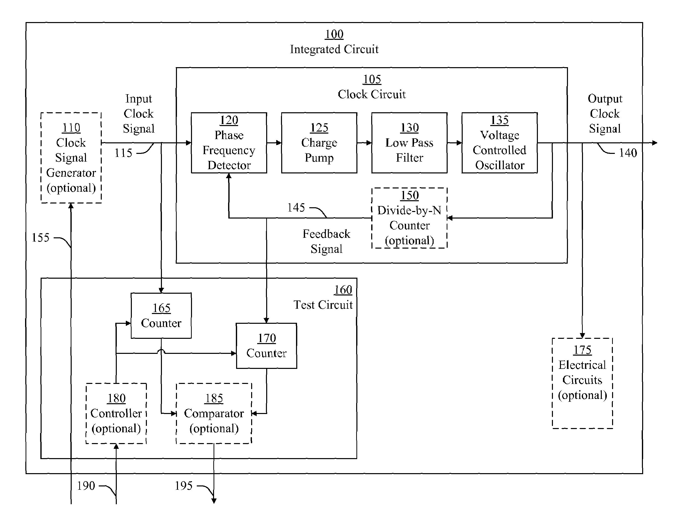
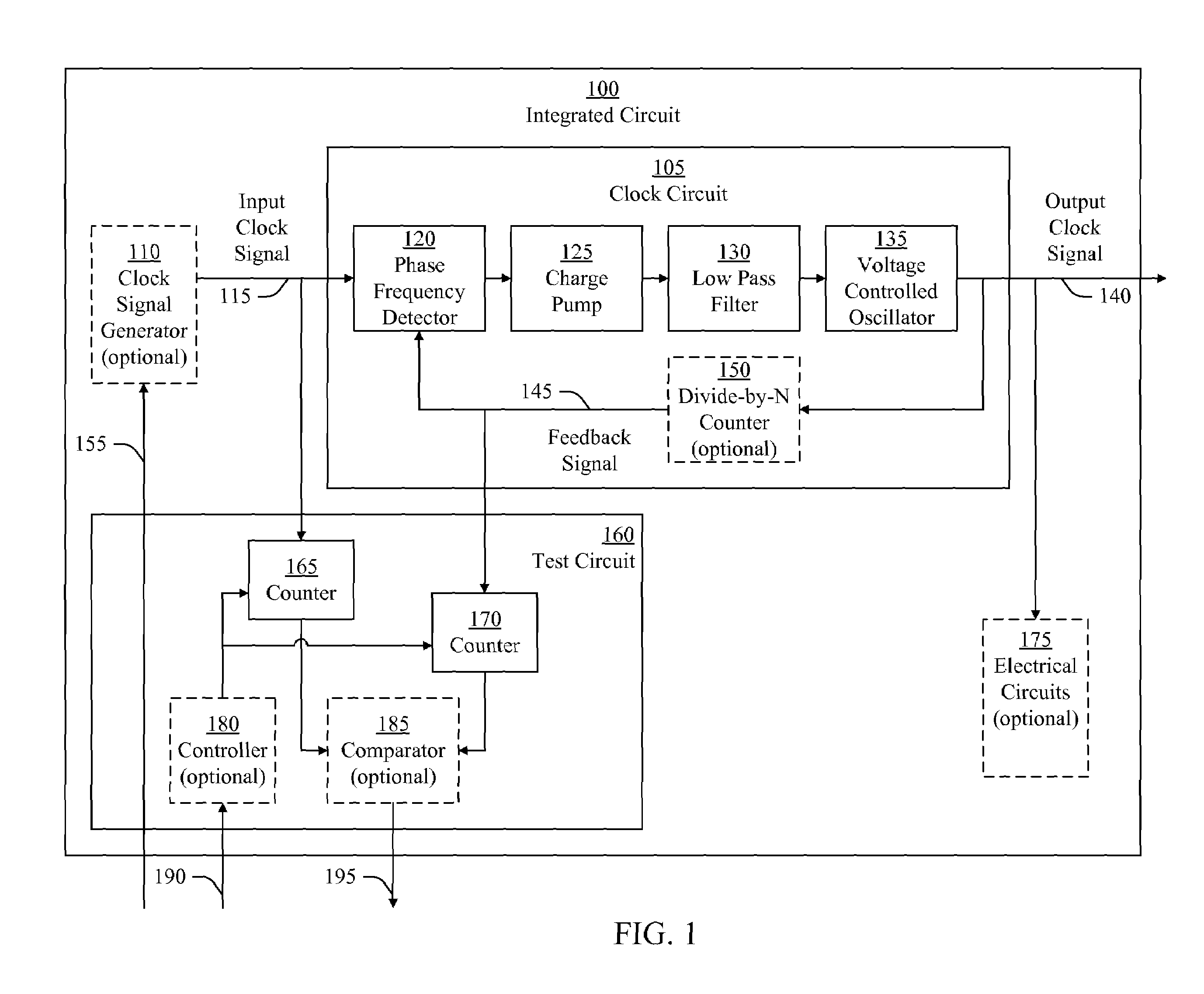
[0020]In various embodiments, an input clock signal to a clock circuit is set to an elevated frequency, which is higher than a specified frequency of the input clock signal. A number of clock cycles of the input clock signal in a test interval are counted to within a tolerance of the elevated frequency. The tolerance of the elevated frequency is higher than a tolerance of the specified frequency. Further, a number of clock cycles of a feedback clock signal of the clock circuit are counted in the test interval. The number of clock cycles of the input clock signal and the feedback clock signal are compared to determine whether a frequency of the output clock signal is above an output threshold frequency. Because the tolerance of the elevated frequency is higher than the tolerance of the specified frequency, the test interval needed for counting the number of clock cycles to within the tolerance of the elevated frequency is less than a test interval needed for counting the number of cl...


PUM


Abstract

A test circuit determines whether a frequency of an output clock signal of a clock circuit is above an output threshold frequency. An input clock signal of the clock circuit is set to an elevated frequency that is higher than a specified frequency. A first counter counts the number of clock cycles of the input clock signal in a test interval to within a tolerance of the elevated frequency. The tolerance of the elevated frequency is higher than a tolerance of the specified frequency. A second counter counts the number of clock cycles of a feedback clock signal in the test interval. A comparator determines whether the frequency of the output clock signal is above the output threshold frequency based on the number of clock cycles of the input clock signal and the number of clock cycles of the feedback clock signal.

Description

BACKGROUND[0001]1. Field of the Invention[0002]The present invention generally relates to testing integrated circuits, and more particularly to testing clock circuits implemented in integrated circuits.[0003]2. Description of Related Art[0004]During manufacturing of an integrated circuit, various tests are performed to determine whether various circuits in the integrated circuit conform to desired specifications. Some of these circuits are clock circuits that generate an output clock signal based on an input clock signal and a feedback clock signal. The feedback clock signal is derived from the output clock signal and is used to generate the output clock signal at a desired frequency. One type of clock circuit that generates an output clock signal based on an input clock signal and a feedback clock signal is a phase-locked loop circuit. A phase-locked loop circuit locks a frequency and phase of a feedback clock signal to a frequency of an input clock signal. Another type of clock ci...

Claims


Application Information

Patent Timeline
IPC IPC(8): G01R23/14
CPCG01R31/31727H03L7/08
Inventor FANG, AL XUEFENGXU, CHAO
Owner INTEGRATED DEVICE TECH INC
Learn More