
Vehicle steering apparatus and vehicle steering method

a steering apparatus and vehicle technology, applied in the direction of electric steering, vehicle components, power driven steering, etc., can solve the problems the system is complex, and it is difficult to achieve the optimal assist characteristics of the steering torque on the driver with the conventional vehicle steering apparatus, so as to achieve stable suppression of pulling, increase and achieve the effect of increasing the steering load on the driver

Inactive Publication Date: 2010-07-13
NISSAN MOTOR CO LTD
View PDF12 Cites 12 Cited by
  • Summary
  • Abstract
  • Description
  • Claims
  • Application Information

AI Technical Summary

Benefits of technology

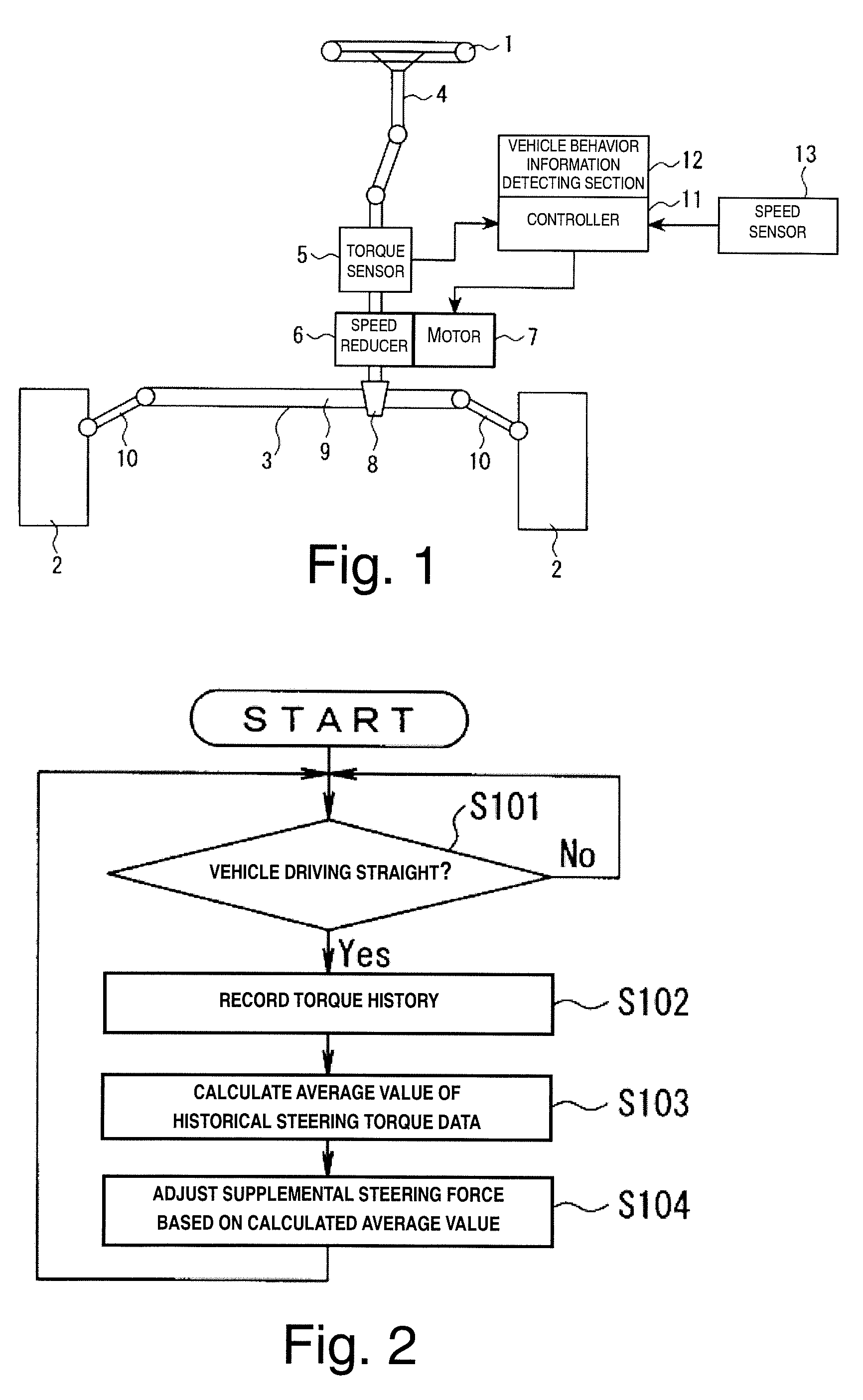
The present invention provides a simplified vehicle steering apparatus that can stably suppress pulling of the vehicle without increasing the steering load on the driver. The apparatus includes a steering system and a supplemental steering force applying device. The supplemental steering force applying device detects the steering torque and the rectilinear driving condition of the vehicle, and adjusts the supplemental steering force in a direction canceling the pulling force imparted on the vehicle during the rectilinear driving condition. This results in a more stable and efficient steering system for the vehicle.

Problems solved by technology

It has been discovered that in conventional vehicle steering apparatuses in which the supplemental steering force is controlled so as to compensate for the estimated disturbances such as in the first reference mentioned above, the system tends to be complex since the conventional vehicle steering apparatus attempts to suppress pulling of the vehicle without taking into account that the disturbances include routine or constant disturbances (e.g., the disturbances originating in the vehicle generated by lateral differences in suspension geometry and / or lateral differences in tire conicity and the like) and temporary disturbances such as crosswinds and the like.
Therefore, it is difficult to achieve optimum assist characteristics of the steering torque on the driver with the conventional vehicle steering apparatus.
Therefore, the steering load on the driver increases when such conventional vehicle steering apparatus is used.

Method used


Image

  • Vehicle steering apparatus and vehicle steering method
  • Vehicle steering apparatus and vehicle steering method
  • Vehicle steering apparatus and vehicle steering method

Examples


second embodiment

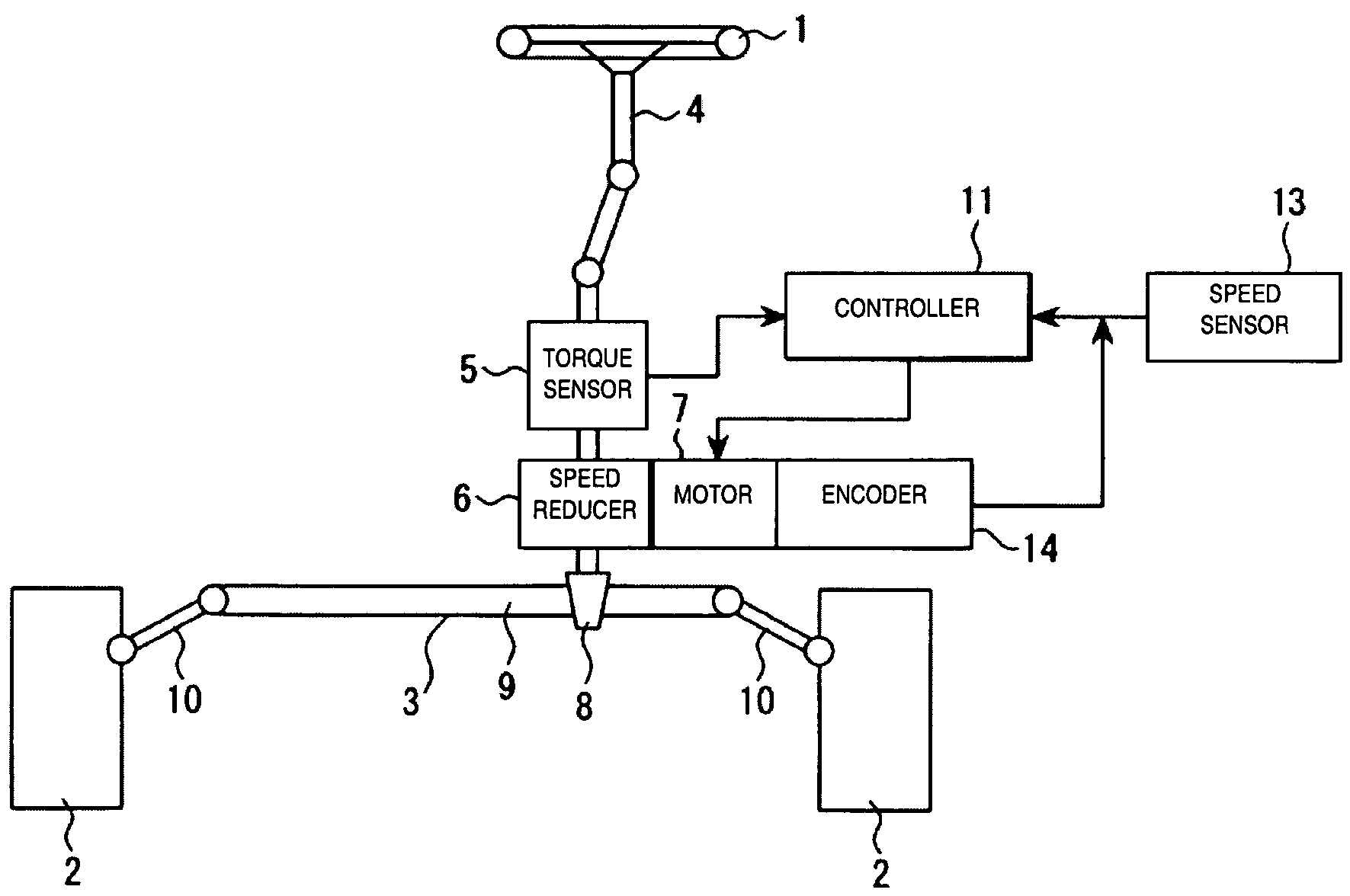
[0065]Referring now to FIGS. 4 to 7, a vehicle steering apparatus in accordance with a second embodiment will now be explained. In view of the similarity between the first and second embodiments, the parts of the second embodiment that are identical to the parts of the first embodiment will be given the same reference numerals as the parts of the first embodiment. Moreover, the descriptions of the parts of the second embodiment that are identical to the parts of the first embodiment may be omitted for the sake of brevity.

[0066]FIG. 4 is a schematic diagram of the vehicle steering apparatus of the second embodiment. The description below focuses on explaining structural parts and operations of the second embodiment that are different from the first embodiment illustrated in FIG. 1. The vehicle steering apparatus of the second embodiment differs from the vehicle steering apparatus of the first embodiment in that the rectilinear driving condition of the vehicle is determined based on a...

third embodiment

[0081]Referring now to FIGS. 8 and 9, a vehicle steering apparatus in accordance with a third embodiment will now be explained. In view of the similarity between the second and third embodiments, the parts of the third embodiment that are identical to the parts of the second embodiment will be given the same reference numerals as the parts of the second embodiment. Moreover, the descriptions of the parts of the third embodiment that are identical to the parts of the second embodiment may be omitted for the sake of brevity.

[0082]The vehicle steering apparatus of the third embodiment differs from the vehicle steering apparatus of the second embodiment in that the pulling direction of the vehicle is detected when the driver is not holding the steering wheel 1 or is not steadily holding the steering wheel 1, and the supplemental steering force is imparted in a direction suppressing pulling of the vehicle. The structure of the vehicle steering apparatus of the third embodiment is identic...

fourth embodiment

[0091]Referring now to FIGS. 10 to 12, a vehicle steering apparatus in accordance with a fourth embodiment will now be explained. In view of the similarity between the first and fourth embodiments, the parts of the fourth embodiment that are identical to the parts of the first embodiment will be given the same reference numerals as the parts of the first embodiment. Moreover, the descriptions of the parts of the fourth embodiment that are identical to the parts of the first embodiment may be omitted for the sake of brevity.

[0092]FIG. 10 is a schematic diagram of the vehicle steering apparatus of the fourth embodiment. The description below focuses on explaining structural parts and operations of the second embodiment that are different from the first embodiment illustrated in FIG. 1. The vehicle steering apparatus of the fourth embodiment differs from the vehicle steering apparatus of the first embodiment in that a steering neutral point (a point in which a sufficient amount of torq...


PUM


Abstract

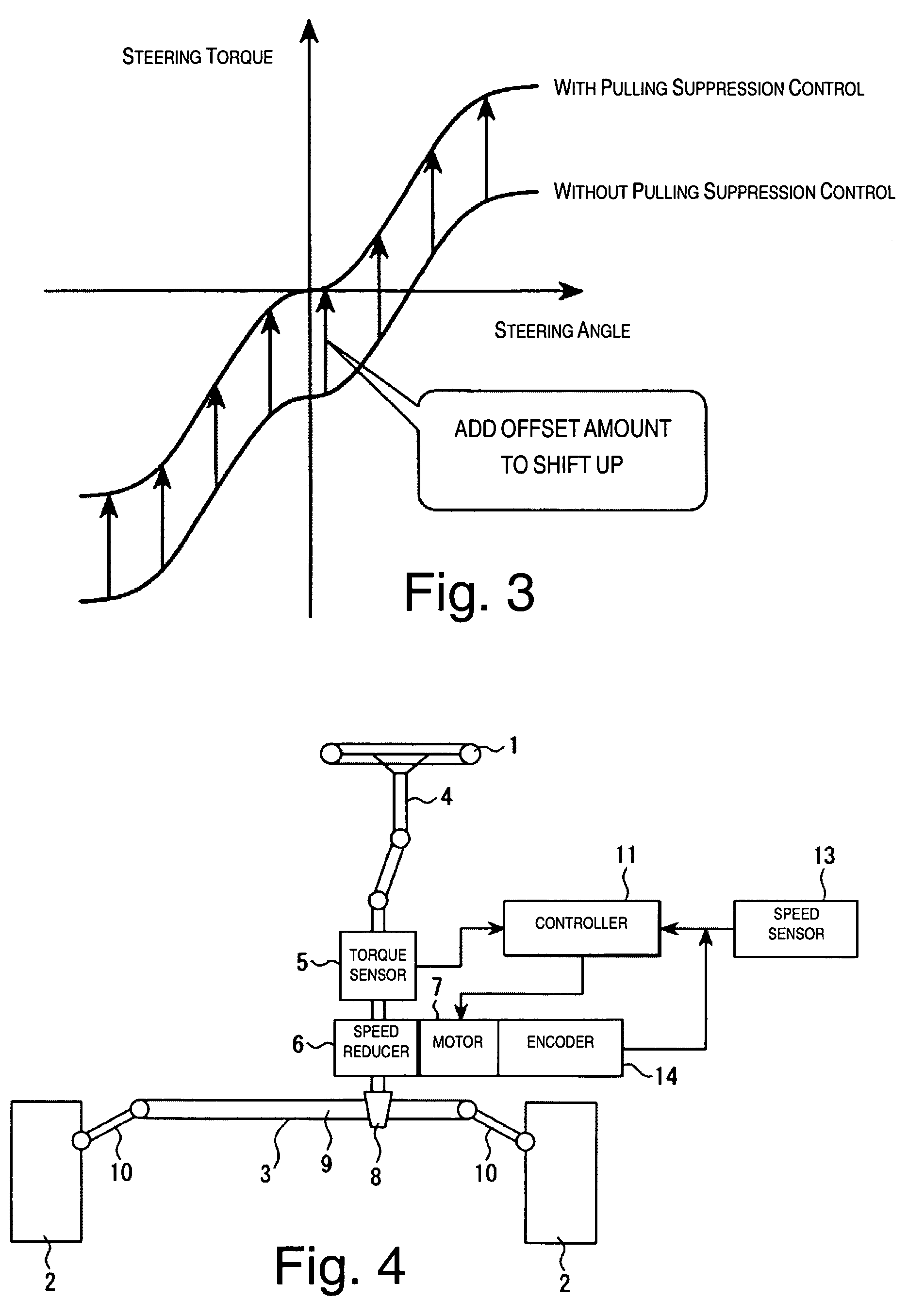
A vehicle steering apparatus includes a vehicle steering system and a supplemental steering force applying device. The supplemental steering force applying device is configured and arranged to apply a supplemental steering force to the vehicle steering system to reduce a steering load on the operator. The supplemental steering force applying device includes a steering torque detecting section, a rectilinear driving condition detecting section, a pulling suppression control section. The rectilinear driving condition detecting section is configured and arranged to detect a rectilinear driving condition of the vehicle. The pulling suppression control section is configured and arranged to adjust the supplemental steering force in a direction canceling a pulling force imparted on the vehicle during the rectilinear driving condition by using a pulling suppression force calculated based on historical data of the steering torque detected during the rectilinear driving condition.

Description

CROSS-REFERENCE TO RELATED APPLICATIONS[0001]This application claims priority under 35 U.S.C. §119 to Japanese Patent Application Nos. 2005-223554 and 2006-058454. The entire disclosures of Japanese Patent Application Nos. 2005-223554 and 2006-058454 are hereby incorporated herein by reference.BACKGROUND OF THE INVENTION[0002]1. Field of the Invention[0003]The present invention relates to a vehicle steering apparatus and a vehicle steering method configured and arranged to control a supplemental steering force to reduce a steering load on a driver.[0004]2. Background Information[0005]Japanese Laid-Open Patent Publication No. 2001-1923 discloses an example of conventional vehicle steering apparatus that is configured and arranged to estimate various inputs such as crosswinds, road cant, and poor road conditions as dynamic disturbances, and to control a supplemental steering force so as to compensate for the estimated disturbances. Moreover, Japanese Laid-Open Patent Publication 2000-...

Claims


Application Information

Patent Timeline
Patent Type & Authority Patents(United States)
IPC IPC(8): B62D5/04
CPCB62D5/0472B62D6/04
Inventor SHIOZAWA, YUUKIMOURI, HIROSHIKUBOTA, MASAHIROSHIRATO, RYOTANAGAE, NAMIWATANABE, MASAYUKI
Owner NISSAN MOTOR CO LTD
Learn More