Light-emitting diode assembly and method of fabrication

a technology of light-emitting diodes and assemblies, which is applied in the direction of transportation and packaging, semiconductor devices for light sources, lighting and heating apparatus, etc., can solve the problems of large thermal resistance of pcb, significant reduction in the lifespan of leds, and inability to quickly and efficiently remove hea

Inactive Publication Date: 2010-07-13
HON HAI PRECISION IND CO LTD
View PDF20 Cites 77 Cited by
  • Summary
  • Abstract
  • Description
  • Claims
  • Application Information

AI Technical Summary

Problems solved by technology

Furthermore, as the PCB is made of FR-4, which is produced by glass fiber impregnation into ethoxyline, thermal resistance of the PCB is very large.
The heat thus cannot be rapidly and efficiently removed, which results in significant reductions in the lifespan of the LEDs.

Method used


Image

  • Light-emitting diode assembly and method of fabrication
  • Light-emitting diode assembly and method of fabrication
  • Light-emitting diode assembly and method of fabrication

Examples


first embodiment

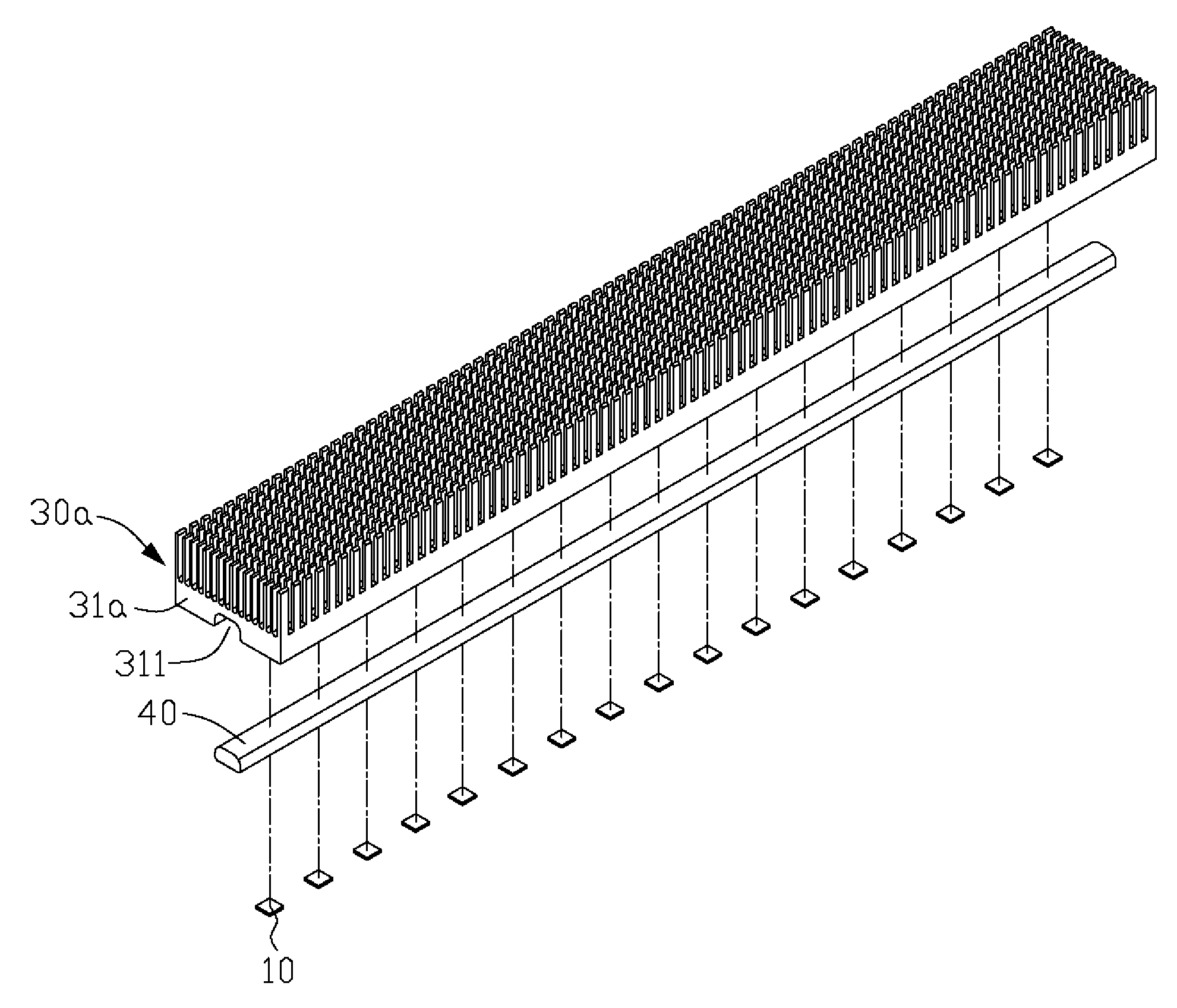
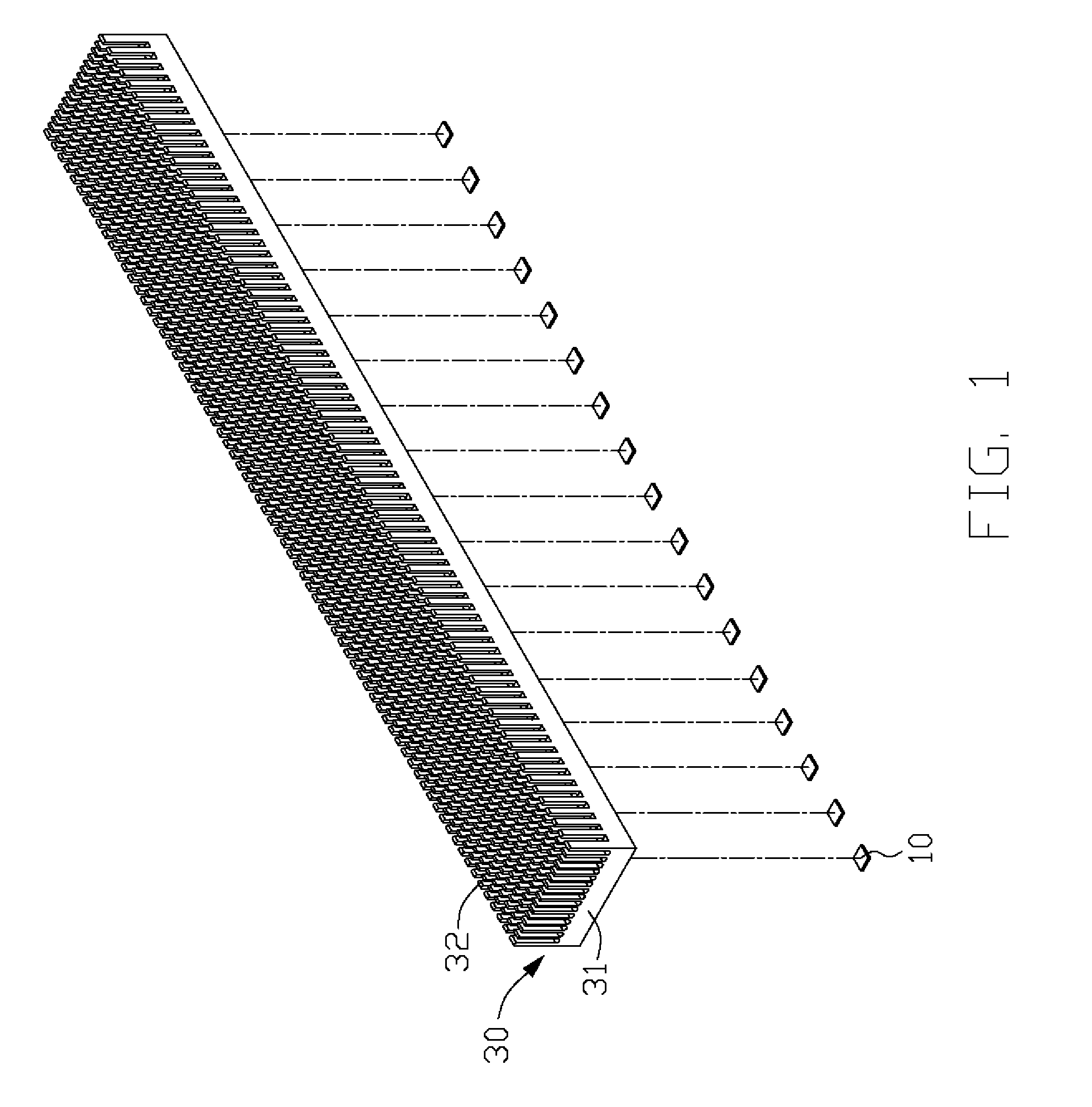
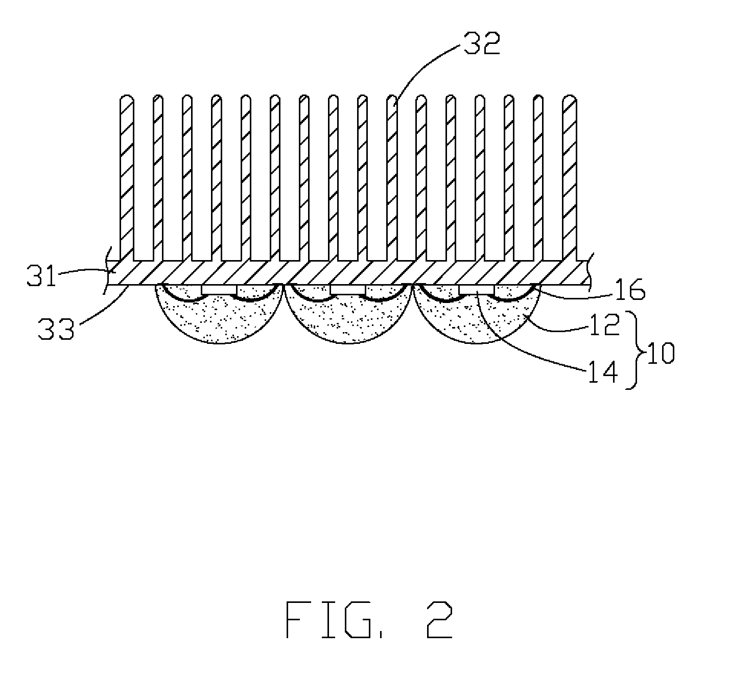
[0021]FIGS. 1-2 illustrate a light-emitting diode (LED) assembly in accordance with the present invention. The LED assembly includes a plurality of LEDs 10, and a heat dissipation device for removing heat generated by the LEDs 10. In this embodiment, the heat dissipation device is a fin-type heat sink 30. The heat sink 30 is made of highly thermally conductive material, such as copper, aluminum, or their alloys. The heat sink 30 as shown in this embodiment is an extruded aluminum heat sink, including a chassis 31 and a plurality of pin fins 32 extending upwardly from the chassis 31. Apparently, the fins 32 are used for increasing the heat dissipation area of the heat sink 30. Alternatively, the fins 32 can be flat shaped. The fins 32 and the chassis 31 can be formed separately, and then connected together by soldering.

[0022]Referring also to FIG. 3, a bottom surface of the chassis 31 of the heat sink 30 forms a connecting surface 33 for the LEDs 10 to be mounted thereon. Circuitry 2...

fourth embodiment

[0028]FIG. 7 shows the LED assembly, which includes a heat dissipation device having a heat spreader 50, a heat pipe 40d and a heat sink 30d. Top and a bottom surfaces of the heat spreader 50 form connecting surfaces 53d for the LEDs 10 to be mounted thereon. The circuitry 20 of FIG. 3 is directly formed on each of the connecting surfaces 53d of the heat spreader 50 with the LED dies 14 being electrically connected thereto. An evaporating section 41 of the heat pipe 40d is received in the heat spreader 50 to absorb the heat generated by the LEDs 10. The heat sink 30d includes a plurality of flat fins 32d. Each fin 32d defines a hole (not labeled) in a central portion thereof. Cooperatively the holes of the fins 32d define a groove 38 for extension of a condensing section (not labeled) of the heat pipe 40d therethrough. Thus the fins 32d surround the condensing section of the heat pipe 40d, and the heat of the heat pipe 40d absorbed from the LEDs 10 can be more evenly distributed ove...

fifth embodiment

[0029]FIG. 8 illustrates the present LED assembly, in which a vapor chamber 30b is provided. The vapor chamber 30b has a much larger size than the heat pipe 40, 40c, 40d shown in the previous embodiments. The vapor chamber 30b has a chassis 31b with a top surface from which a plurality of fins 32b extend upwardly and a flat bottom surface to form a connecting surface 313 on which the circuitry 20 of FIG. 3 is formed directly. The LEDs 10 are electrically connected with the circuitry 20 and are maintained in thermal and physical contact with the connecting surface 313 of the vapor chamber 30b. The vapor chamber 30b also contains a working fluid therein and also employs a phase change mechanism to transfer heat. The heat from the LED dies 14 is directly transferred to the vapor chamber 30b and then is transferred from the vapor chamber 30b to the fins 32b for dissipation. As the vapor chamber 30b has a much larger size, more LEDs 10 can be provided to the assembly so as to increase th...


PUM

PropertyMeasurementUnit
shapeaaaaaaaaaa
thermal resistanceaaaaaaaaaa
heat transfer coefficientaaaaaaaaaa

Abstract

A light-emitting diode (LED) assembly includes a heat dissipation device (30) and at least one LED (10). The heat dissipation device has a connecting surface (33) with circuitry (20) being directly formed thereon. The at least one LED is electrically connected with the circuitry, and is maintained in thermal and mechanical contact with the connecting surface to dissipate heat generated thereby through the heat dissipation device. A method for making the LED assembly includes steps of: (A) providing a heat dissipation device having a surface for the LED to be mounted thereon; (B) insulating the surface; (C) forming circuitry on the insulated surface directly to obtain a connecting surface; (D) attaching the LED to the connecting surface of the heat dissipation device thermally and mechanically, and connecting the LED with the circuitry electrically to form the LED assembly.

Description

BACKGROUND OF THE INVENTION[0001]1. Field of the Invention[0002]The present invention relates generally to light-emitting diode (LED) assemblies, and more particularly to an LED assembly with improved heat dissipation ability so that heat generated by the LEDs of the assembly can be effectively removed. The present invention relates also to a method for making the LED assembly.[0003]2. Description of Related Art[0004]Light-emitting diode (LED) is a highly efficient light source currently used widely in such field as automobiles, screen displays, and traffic light indicators. When the LED gives off light, heat is also produced.[0005]Generally an LED assembly includes a plurality of LEDs mounted on and electronically connected with a printed circuit board (PCB). A heat sink made of metal, such as aluminum or copper, is arranged under the PCB to remove the heat generated by the LEDs. To reduce thermal resistance between the heat sink and the PCB, thermal interface material, such as the...

Claims


Application Information

Patent Timeline
Patent Type & Authority Patents(United States)
IPC IPC(8): F21V25/06
CPCF21K9/00F21V29/006F21V29/402F21V29/763F21V29/80H01L33/64H01L33/648H05K1/0272Y10T29/49002H05K1/053F21V29/51F21V29/59F21V29/89
Inventor HU, TSENG-HSIANGLIN, YEU-LIHTAN, LI-KUANG
Owner HON HAI PRECISION IND CO LTD
Why Eureka
Try Eureka