Triple-mode cavity filter having a metallic resonator

a cavity filter and metallic resonator technology, applied in the direction of resonators, electrical equipment, waveguides, etc., can solve the problems of increasing the cost of overall filters, so as to achieve the effect of reducing cost and facilitating design and manufactur

Active Publication Date: 2010-07-13
RFS TECH INC +1
View PDF7 Cites 12 Cited by
  • Summary
  • Abstract
  • Description
  • Claims
  • Application Information

AI Technical Summary

Problems solved by technology

Because the enclosed cavity acts as a waveguide, the pattern of electromagnetic waves is limited to those waves that can fit within the walls of the waveguide.
Fabrication of dielectric resonators with expensive ceramic materials would make the overall filter more costly.
The dielectric cube also tends to produce spurious resonances near the resonator's desired operating frequency.
While suppression would compensate for the spurious modes, it would also greatly increase the insertion loss of the resonator.
An increase in insertion loss is proportional to a decrease in transmitted power from the resonator.
Therefore, the elimination of spurious modes also reduces the overall signal strength.

Method used


Image

  • Triple-mode cavity filter having a metallic resonator
  • Triple-mode cavity filter having a metallic resonator
  • Triple-mode cavity filter having a metallic resonator

Examples


Embodiment Construction

[0032]Referring now to the drawings, in which like numerals refer to like components or steps, there are disclosed broad aspects of various exemplary embodiments.

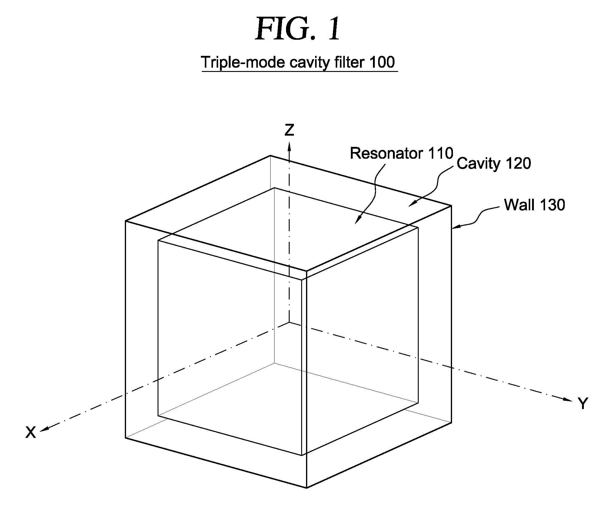
[0033]FIG. 1 is a perspective view of an exemplary triple-mode cavity resonator 100. In various exemplary embodiments, resonator 110 is a metallic block located entirely within the conductive enclosure of cavity resonator 100 having at least one wall 130 that defines a cavity 120 for confining electromagnetic waves. Resonator 110 may be entirely enclosed within cavity 120, such that resonator 110 does not touch the at least one wall 130. Cavity 120 may be implemented as a rectangular parallelepiped having a top surface, a bottom surface, and four side walls. Alternatively, cavity 120 may be cylindrical, spherical, or designed in another appropriate shape as determined by one of ordinary skill in the art.

[0034]Cavity 120 resonates at certain frequencies due to the internal reflections of electromagnetic waves at the air / meta...


PUM

PropertyMeasurementUnit
dielectric constantaaaaaaaaaa
frequency responseaaaaaaaaaa

Abstract

A triple-mode filter is disclosed, the triple-mode filter including a cavity for confining electromagnetic waves and a metallic block acting as a resonator within that cavity. The metallic block does not contact the conductive walls of the cavity, but is instead suspended by a support element. Triple-mode resonators may be combined to produce bandpass filters having three or more poles. In other configurations, triple-mode cavity metallic resonators may be coupled to triple-mode cavity ceramic resonators or to combline resonators to achieve various filtering functions and performances suitable for different applications.

Description

BACKGROUND OF THE INVENTION[0001]1. Field of the Invention[0002]This invention relates generally to triple-mode cavity filters for microwave and radio frequency signals and, more particularly, to cavity filters using metallic resonators.[0003]2. Description of the Related Art[0004]Wireless communication systems often require devices to select signals within predetermined frequency bands. When these devices are implemented as bandpass filters, users can select a desired range of frequencies, known as a passband, and discard signals from frequency ranges that are either higher or lower than the desired range. It is particularly important for bandpass filters to achieve high out-of-band rejection, attenuating signals outside the passband to emphasize the desired frequency range.[0005]Cavity resonators are devices frequently used to implement bandpass filters. A cavity resonator confines electromagnetic radiation within a solid structure, typically formed as a rectangular parallelepiped...

Claims


Application Information

Patent Timeline
Patent Type & Authority Patents(United States)
IPC IPC(8): H01P1/20H01P7/10
CPCH01P1/2082
Inventor SALEHI, HAMID REZA
Owner RFS TECH INC
Why Eureka
Try Eureka