

Skylight system
a skylight system and tapered tubing technology, applied in the direction of photovoltaic supports, instruments, optical elements, etc., can solve the problems of wasting installation time, shipping and storage, product design, etc., and consuming time to secure the outer dome to the flashing with screws or bolts
Inactive Publication Date: 2010-07-20
SUNBULB
View PDF28 Cites 30 Cited by
- Summary
- Abstract
- Description
- Claims
- Application Information
AI Technical Summary
Benefits of technology
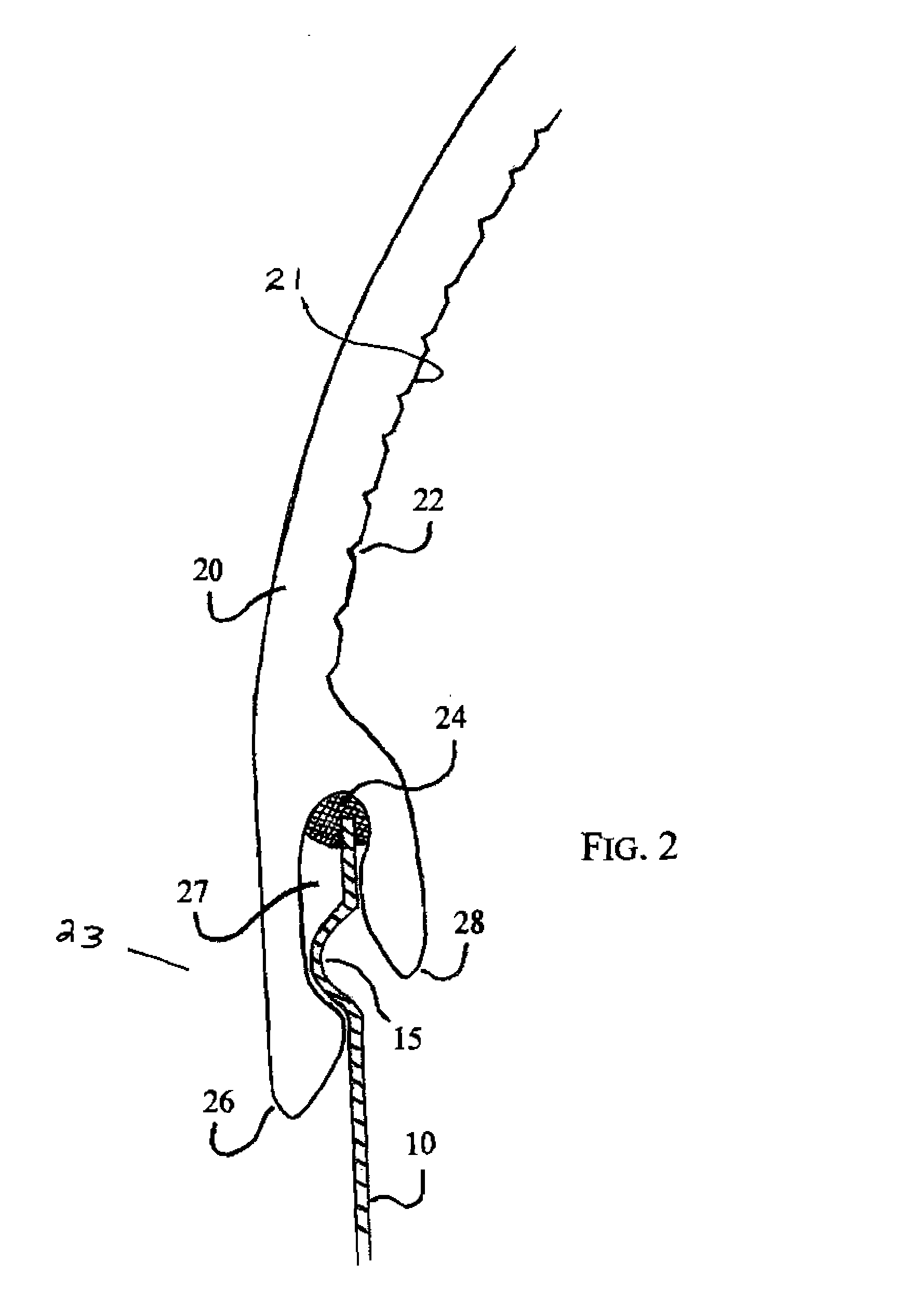
[0027]A primary advantage of the present invention is that it requires no roof flashing materials, is safe, and is sealed.
is that it requires no roof flashing materials, is safe, and is sealed.
Problems solved by technology
There are many problems with this type of system, namely product design, wasted installation time, shipping and storage.
Securing the outer dome to the flashing with screws or bolts consumes time and tends to crack the outer dome at the points of pressure.
The holes allow the system to breathe, exhaling in the heat of the day, and inhaling moisture, dust, bugs, and other contaminates at night, which in time ruins the highly reflective light tube.
The flashing is a waste of time and money.
The light tube's straight cylindrical shape causes many problems.
If shipped to the job site already assembled, much space is taken up for this shipping.
This causes a safety hazard and is unsightly.
None of these prior art systems describe a tapered skylight, with the taper being wider at the top than the bottom.
Nor do any of these prior art system disclose a permanently sealed skylight system.
Method used
View moreImage
Smart ImageViewing Examples

Examples
example
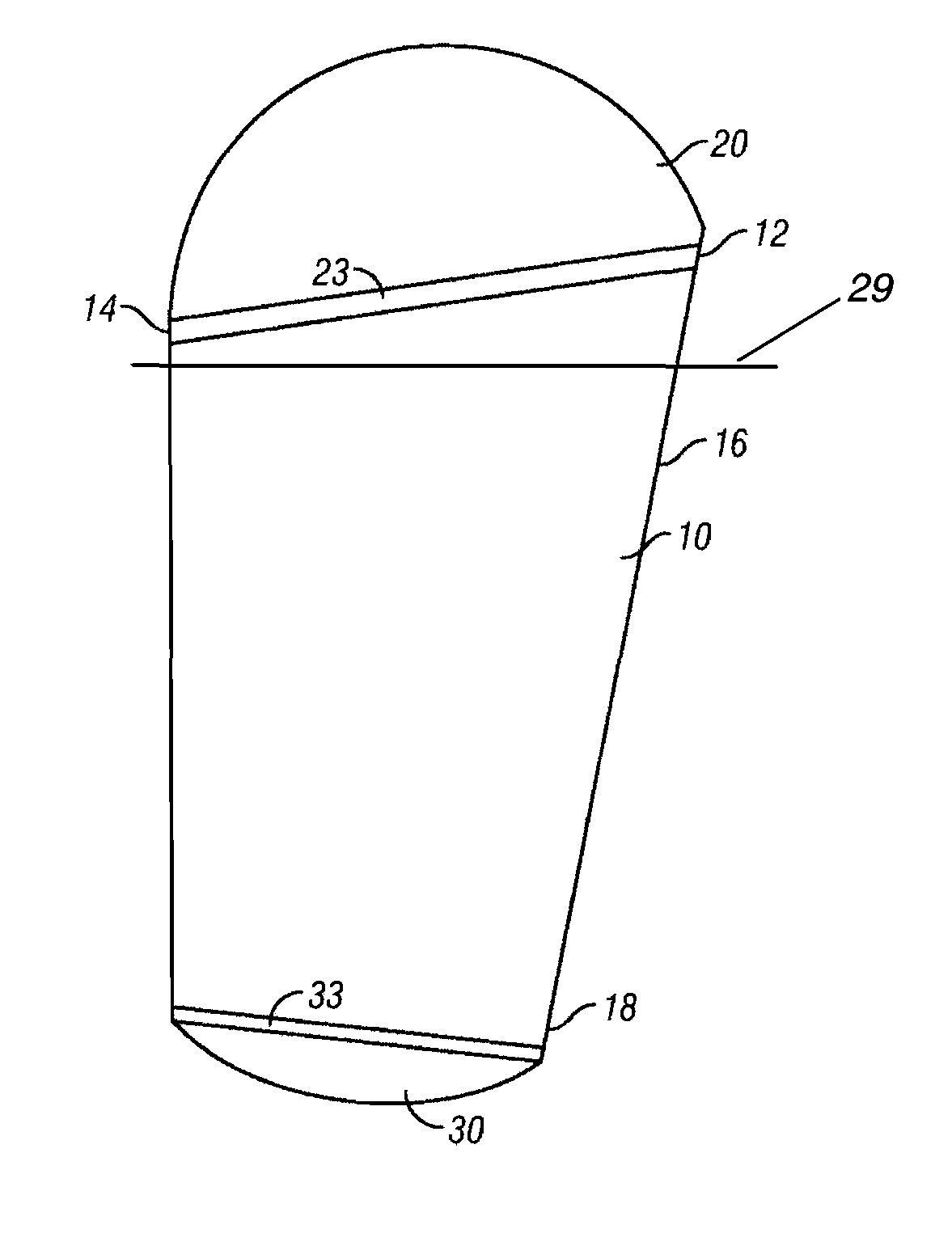
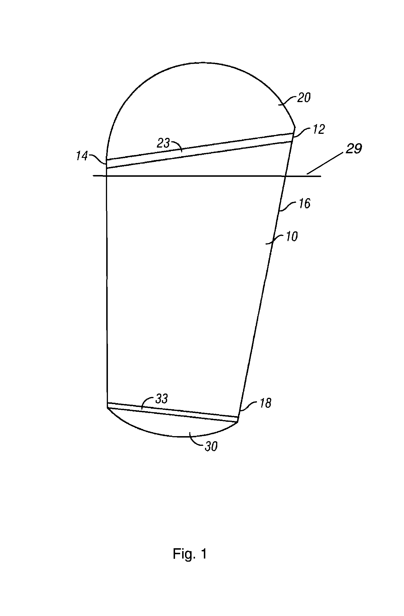
[0049]A skylight was constructed as follows. First, the completely prismatic top dome was made from polycarbonate plastic that was squared and tapered in shape with an inner lip that fit the light tube tightly to the dome. Second, a square flashing light tube that was tapered, from a larger top to a smaller bottom, was made from heavy gauge sheet aluminum, which became the “flashing” and the highly reflective interior surface. Next, a bottom diffuser was cemented with sealants to the aluminum light tube to create a permanently sealed unit. The dimensions of this skylight were 24″×24″×5″ height for the top dome; 24″×24″ at the top of the taper, 20″×20″ on the bottom, and 30″ in height; and the bottom diffuser was 20″×20″×2″ depth.
Login to View More PUM
 Abstract
A skylight system comprising a tapered light tube with the taper wider at the top than at the bottom and a permanently sealed skylight system. A diffused top dome and a diffuser bottom are attached to the light tube on site. No typical roof flashing is required during installation.
Description
CROSS-REFERENCE TO RELATED APPLICATIONS[0001]This application claims the benefit of the filing of U.S. Provisional Patent Application Ser. No. 60 / 444,128, entitled “Skylight”, filed on Jan. 31, 2003, and the specification thereof is incorporated herein by reference.BACKGROUND OF THE INVENTION[0002]1. Field of the Invention (Technical Field)[0003]The present invention relates, generally, to a method and apparatus for a tapered tubular skylight system and a permanently sealed skylight system.[0004]2. Description of Related Art[0005]Note that the following discussion refers to a number of publications by author(s) and year of publication, and that due to recent publication dates certain publications are not to be considered as prior art vis-a-vis the present invention. Discussion of such publications herein is given for more complete background and is not to be construed as an admission that such publications are prior art for patentability determination purposes.[0006]With a typical t...
Claims
Login to View More Application Information
Patent Timeline
 Patent Type & AuthorityPatents(United States)
IPC IPC(8): E04B7/18E04D13/18G02B17/00
CPCE04D13/03E04D2013/034G02B6/0038
InventorHALLIDAY, MICHAEL J.
OwnerSUNBULB