
Spacer arrangement with fusable connector for insulating glass units

a technology of insulating glass units and spacers, which is applied in the direction of building roofs, building components, doors/windows, etc., can solve the problems of ineffective holding of spacer pieces, difficult inserting, and high cost per piece, so as to reduce the insertion effort on the production line, increase the strength of the connector-to-spacer joint, and reduce the cost of ig components

Inactive Publication Date: 2010-07-20
TECHNOFORM GLASS INSULATION HLDG
View PDF41 Cites 17 Cited by
  • Summary
  • Abstract
  • Description
  • Claims
  • Application Information

AI Technical Summary

Benefits of technology

"The patent describes a spacer arrangement with a fusable connector for insulating glass units. This arrangement has several benefits, including stronger connector-spacer joints, easier production, fewer field problems, and lower costs. The patent also describes a spacer frame arrangement with a hollow inner space and a connector section that is inserted into the hollow space and fused with the inner surface of the spacer profile body. The method and apparatus for manufacturing this arrangement are also provided. Overall, the patent provides a solution for improving the manufacturing process of insulating glass units."

Problems solved by technology

These connectors seem to work reasonably well, but they are expensive per piece and several pieces may be needed for each spacer frame.
Also, they can be ineffective in holding the spacer pieces together under specific conditions / circumstances, and they can be difficult to insert because the gripping teeth must be pushed into or along the interior surface of the spacer cross section.
This results in a failed IG unit because of moisture penetration at the open joint.

Method used


Image

  • Spacer arrangement with fusable connector for insulating glass units
  • Spacer arrangement with fusable connector for insulating glass units
  • Spacer arrangement with fusable connector for insulating glass units

Examples


Embodiment Construction

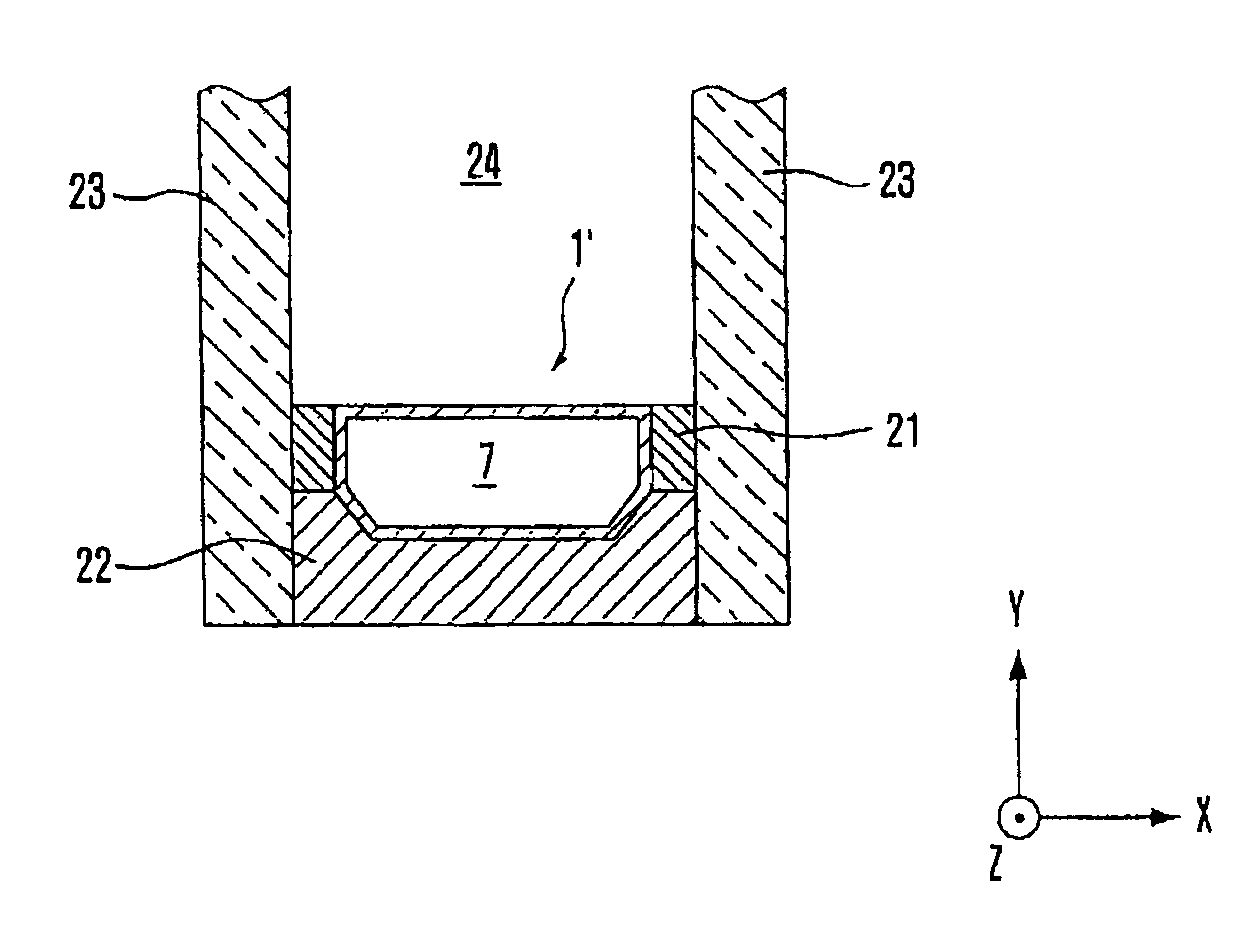
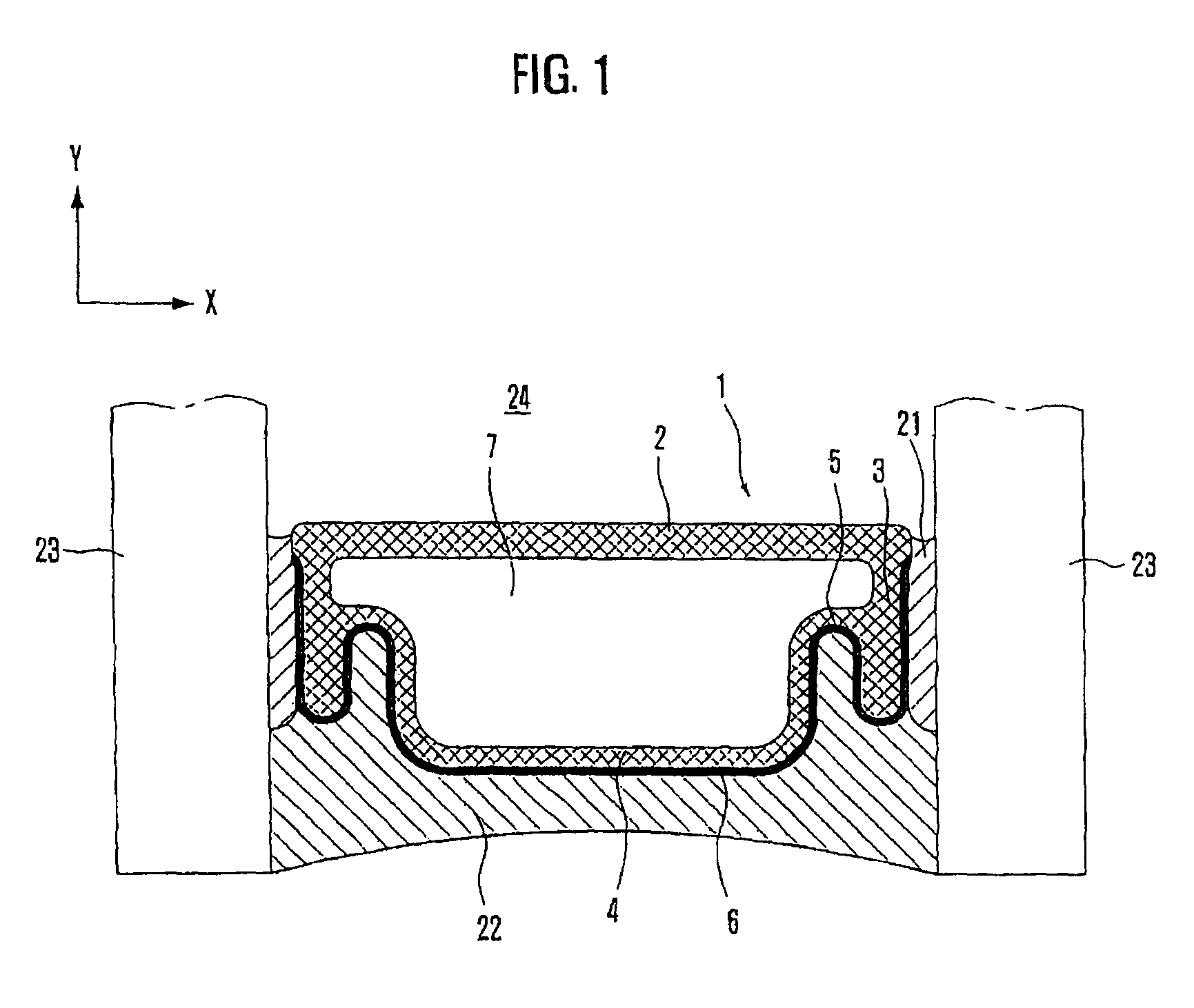
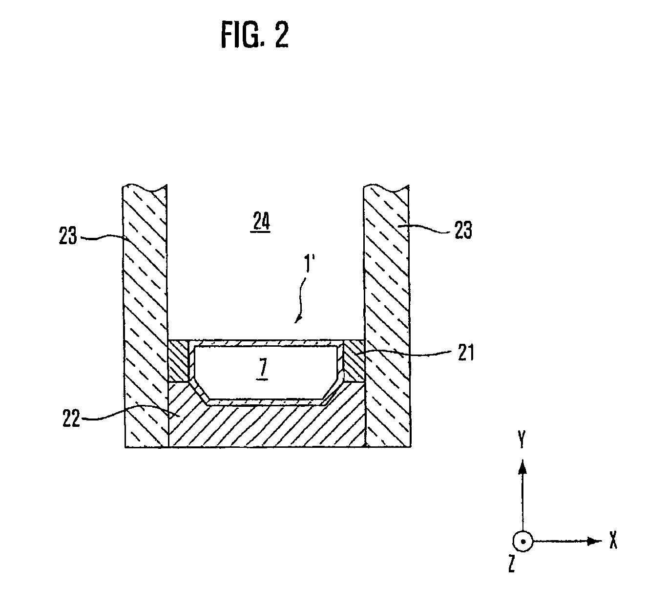
[0046]Referring to FIGS. 1 and 2, the window panes 23 extend in parallel limiting a window pane interspace 24 in planes parallel to the X and Z directions. The outer circumference of the interspace 24 is limited by a spacer frame made of a (cylindrical, preferably hollow) spacer profile 1, 1′ and the adhesive and sealing materials 21, 22, as set in US 2005 / 0100691 A1, the contents of which are incorporated by reference herein.

[0047]In order to provide the spacer profile frame mentioned above, one or plural linear connectors as shown e.g. in FIG. 3 or 5 and / or 90° corner connectors as shown e.g. in FIG. 4 or 6 are suitably used.

[0048]As already mentioned above, the TGI spacer profile is an example of a spacer profile representing a plastic metal composite spacer.

[0049]The inside (inner lining) of such a profile is made of an elastically-plastically deformable material wherein preferred in elastically-plastically deformable materials include synthetic or natural materials that undergo...


PUM


Abstract

A spacer frame arrangement for insulating glass units, comprising a spacer profile body extending in a first direction and having a predetermined cross section in a plane perpendicular to the first direction, the predetermined cross section defining a hollow inner space of the spacer profile body with predetermined dimensions in the plane perpendicular to the first direction, and a connector comprising a connector section adapted to be inserted in the first direction into the hollow inner space of the spacer profile body by having a cross sectional shape perpendicular to the first direction which corresponds, with predetermined tolerances, to the cross section of the spacer profile body limiting the hollow inner space, at least the outer surface of the connector section facing the inner surface of the hollow inner space of the spacer profile body after insertion of the same being made of a fusable material, preferably a material fusable by melting the same, wherein the connector section is inserted into the hollow inner space of the spacer profile body and the outer surfaces of the connector section and the inner surface of the spacer profile body facing each other are connected by fusing.

Description

CROSS-REFERENCE TO RELATED APPLICATIONS[0001]This application claims the benefit of U.S. Provisional Application No. 60 / 704,508, filed on Aug. 1, 2005, and U.S. Provisional Application No. 60 / 716,018, filed on Sep. 9, 2005, both of which are incorporated herewith.BACKGROUND OF THE INVENTION[0002]The present invention relates to a spacer arrangement with fusable connector for insulating glass units.[0003]In the field of insulating glass units (hereinafter IG units), the use of a tubular spacer bar to separate panes of glass forming an IG unit, has been around the window industry for many years. It has been common practice, when fabricating a rectangular IG unit, to cut the spacer bar into specific lengths and connect the four spacer pieces with some sort of connector device or corner key to form the corners of the spacer bar arrangement (frame) of the IG unit. The device used to connect the spacer pieces to form a corner, which could be a square corner or some other angled corner, is...

Claims


Application Information

Patent Timeline
Patent Type & Authority Patents(United States)
IPC IPC(8): E04C2/38E04B7/00
CPCE06B3/667E06B3/67308E06B3/9681Y10T403/559Y10T403/55Y10T403/477Y10T156/10
Inventor GALLAGHER, RAYMOND G.
Owner TECHNOFORM GLASS INSULATION HLDG
Learn More