Drive apparatus

a technology of hydraulic drive and drive body, which is applied in the direction of gearing, fluid couplings, tractors, etc., can solve the problems of affecting the ability of the vehicle to complete the turn, and reducing the hydraulic load presented to the hydraulic pump by the motor driving the drive member which has lost traction

Inactive Publication Date: 2010-07-20
TITAN RES & INNOVATIONS
View PDF15 Cites 4 Cited by
  • Summary
  • Abstract
  • Description
  • Claims
  • Application Information

AI Technical Summary

Benefits of technology

[0015]The drive apparatus is analogous in its operation to a mechanical drive apparatus of a four-wheel drive vehicle which has open mechanical differentials so that each of the wheels of the vehicle is able to rotate at a different speed to the other wheels without slipping or dragging along the ground when the vehicle turns.
[0016]The drive apparatus limits the flow of hydraulic fluid through the hydraulic motor of a hydraulic drive assembly whose ground engaging drive member has lost traction so that the rate at which that drive member is driven by the motor does not increase uncontrollably at the expense of the other drive members of the drive apparatus which have not lost traction. This enables the vehicle on which the drive apparatus is installed to turn in a controlled manner at a constant speed even while the vehicle is pulling or otherwise moving a large load.
[0017]The simplicity of the drive apparatus according to the present invention provides the drive apparatus with a significant advantage over many prior art hydraulic drives which have traction control. Unlike many prior art hydraulic drives, the drive apparatus according to the present invention does not rely upon complicated and fragile electronics to control the traction problems associated with conventional hydraulic drives. This means that the drive apparatus according to the present invention is generally more rugged than prior art hydraulic drives which employ electronic traction control and is therefore better able to cope with the harsh environments in which hydraulic drives are often used.
[0020]It is preferred that the drive assemblies of the first pair of drive assemblies and the second pair of drive assemblies are located diagonally opposite to each other because the load of each control valve assembly will remain substantially constant even when the vehicle turns or when the ground engaging drive members on the left, right, front, or back of the vehicle lose traction. Although there will be a difference in the load of the control valve assemblies if diagonally opposed drive members lose traction, the situation where diagonally opposed drive members lose traction is less likely to occur in comparison to both of the drive members on the left, right, front, or rear of the vehicle losing traction. It is desirable to minimise differences in load between the control valve assemblies to ensure that there is no buildup of temperature in one of the control valve assemblies.
[0026]When two hydraulic pumps are used, it is particularly preferable that the drive assemblies of the first pair of drive assemblies and the second pair of drive assemblies are located diagonally opposite to each other as this reduces the volume of hydraulic fluid flowing through the hydraulic balance line and hence reduces the likelihood of a build-up in temperature in the balance line.
[0030]Preferably, the control valve assemblies are hydraulically or mechanically-controlled. It has been found that hydraulically and mechanically-controlled control valve assemblies are less susceptible to failure compared to electronically-controlled control valve assemblies.

Problems solved by technology

A problem with the prior art hydraulic drive apparatus as just described is that if a ground engaging drive member breaks traction with the ground for some reason, the hydraulic load presented to the hydraulic pump by the motor driving the drive member which has lost traction will decrease so that there is less hydraulic resistance to the flow of hydraulic fluid through that motor.
In agricultural applications where a vehicle having a conventional differential drive apparatus including a plurality of ground engaging drive members employs a drawbar to pull a trailing implement, or where the vehicle is working on uneven or steep terrain, losing traction on a full turn is a real problem.
If a drive member on the outside of the turn radius breaks traction, this inhibits the ability of the vehicle to complete the turn.
Hydraulic drives which employ electronic traction control are generally complicated and are prone to experiencing reliability problems.
Also, the fragile electronics of such hydraulic drives are not particularly suited to the harsh working environments in which hydraulic drives are typically employed.
As will be appreciated, failure of an electronic traction control system can compromise the vehicle's ability to operate to maximum capacity or in fact be able to operate at all.
A problem with the hydraulic drive disclosed by Kropp is that it can generate a residual heat load.

Method used


Image

  • Drive apparatus
  • Drive apparatus
  • Drive apparatus

Examples


Embodiment Construction

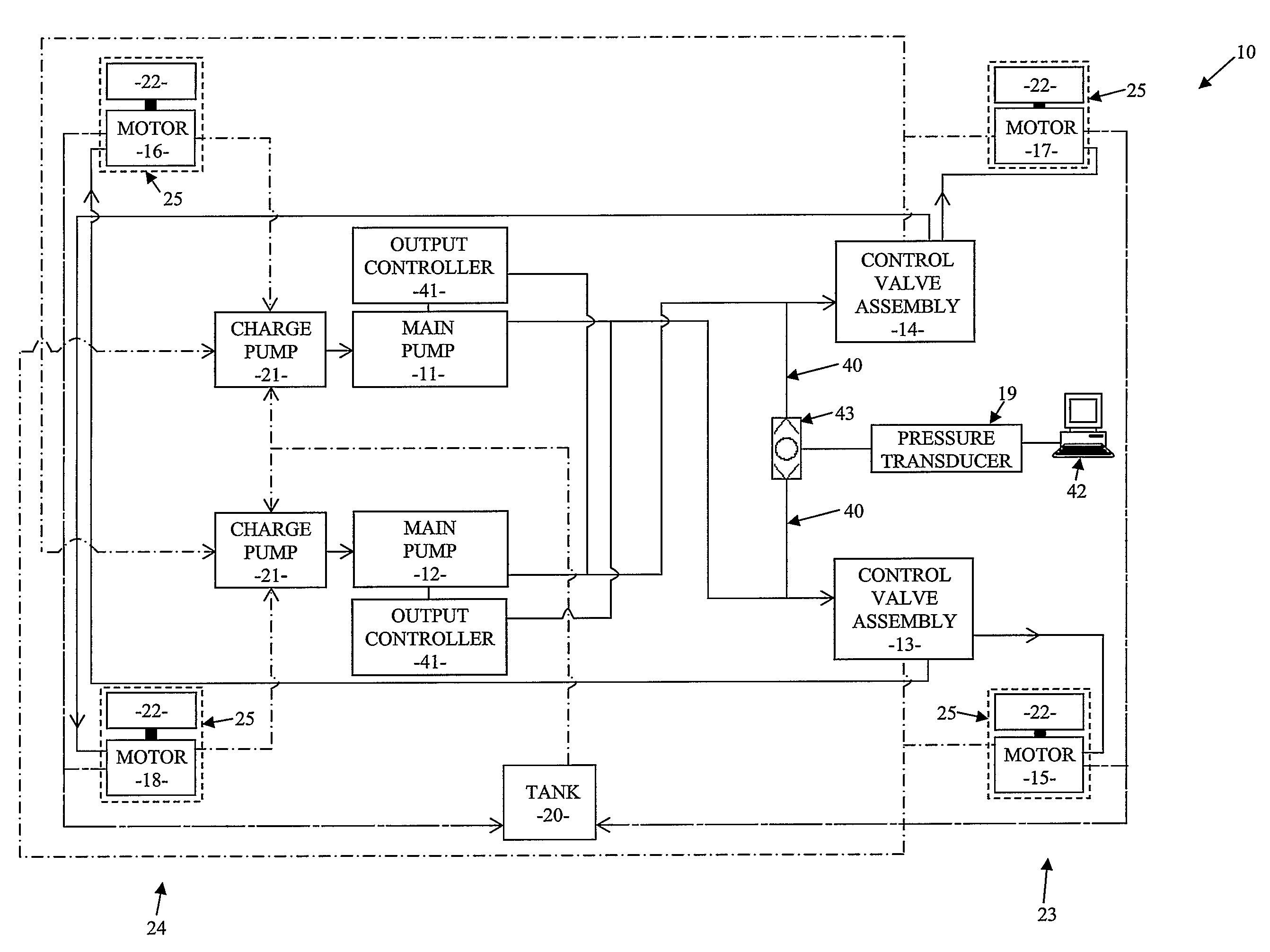
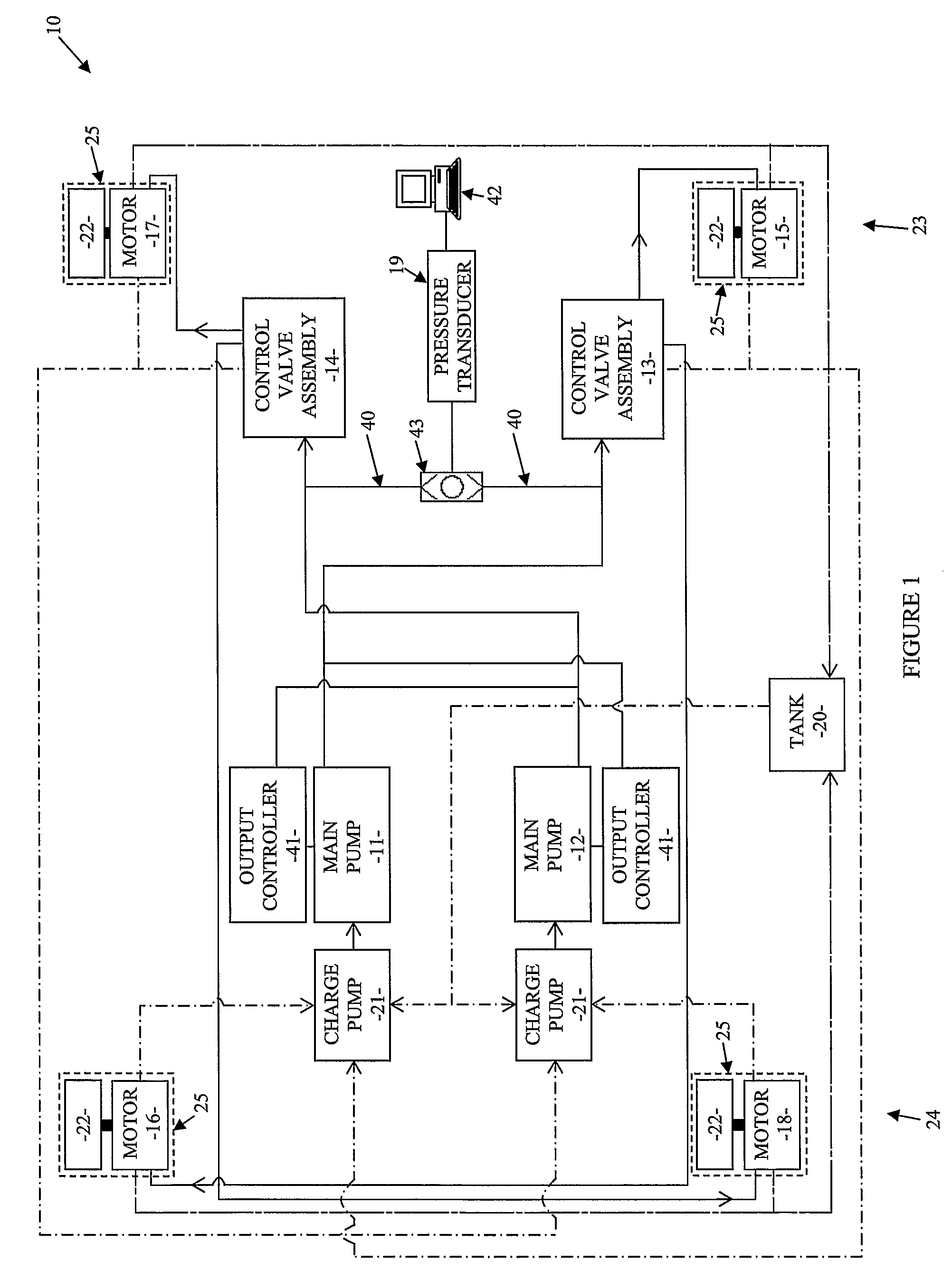
[0047]A drive apparatus 10 according to a preferred embodiment of the present invention is depicted in FIG. 1. Drive apparatus 10 is incorporated into an articulated vehicle (not shown) and is operable to drive or propel the vehicle along the ground.

[0048]Apparatus 10 comprises a first hydraulic main pump 11, a second hydraulic main pump 12, a first hydraulically-controlled hydraulic control valve assembly 13, a second hydraulically-controlled hydraulic control valve assembly 14, hydraulic motors 15, 16, 17, 18, a hydraulic fluid pressure transducer 19, and a hydraulic fluid storage tank 20.

[0049]Hydraulic pumps 11, 12 are identical parallel variable displacement hydraulic piston pumps which are adapted to output a variable flow of hydraulic fluid as required at variable pressure. An inlet of each pump 11, 12 is connected to an outlet of a respective hydraulic charge pump 21.

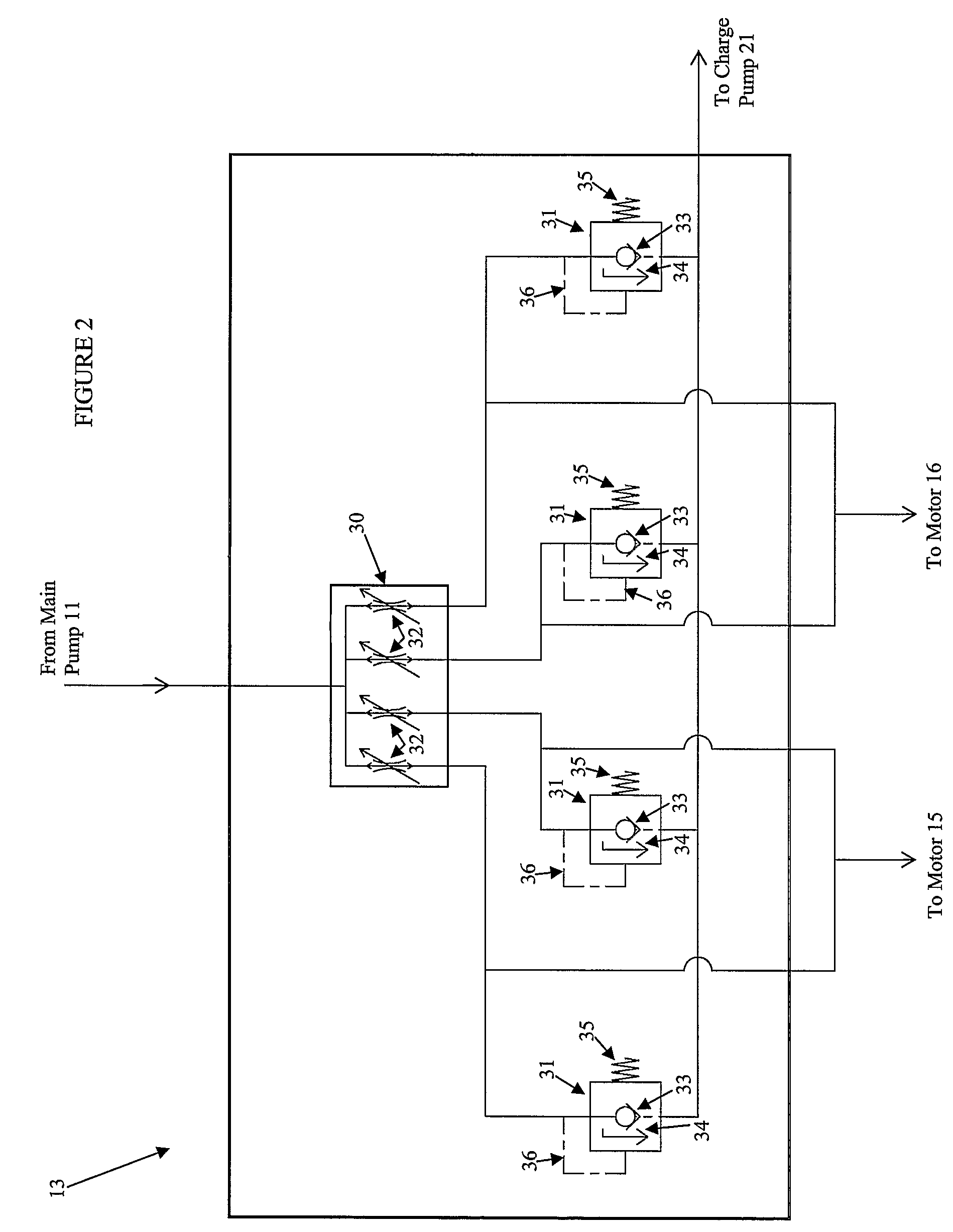
[0050]The hydraulic control valve assemblies 13, 14 are identical to each other, and each assembly 13, 14 inc...


PUM


Abstract

A drive apparatus for a vehicle, the apparatus comprising a hydraulic pump, two control valve assemblies, and two pairs of hydraulic drive assemblies. The control valve assemblies are hydraulically connected in parallel, and in an operational condition hydraulic fluid is pumped through the control valve assemblies by the pump to drive the hydraulic drive assemblies, and wherein each control valve assembly proportionately distributes hydraulic fluid to a respective pair of the hydraulic drive assemblies in response to the hydraulic loads of the respective hydraulic drive assemblies of the respective pairs of hydraulic drive assemblies. In response to a difference in the respective hydraulic loads of the hydraulic drive assemblies of the respective pairs of hydraulic drive assemblies, flow of hydraulic fluid to the hydraulic drive assembly of each of the respective pairs of hydraulic drive assemblies having the lower hydraulic load is limited, and wherein each of the hydraulic drive assemblies includes a ground engaging drive member and at least one hydraulic motor for driving the drive member.

Description

FIELD OF THE INVENTION[0001]The present invention relates generally to hydraulic drive apparatus and, in particular, to hydraulic drive apparatus which are used to propel vehicles.[0002]Although the invention will be described with particular reference to hydraulic drive apparatus which include four ground engaging drive members such as wheels or tracks, it will be appreciated that this is by way of example only and that the invention may be used in relation to hydraulic drive apparatus which have more than four ground engaging drive members and which may have ground engaging drive members other than wheels or tracks.BRIEF DISCUSSION OF THE PRIOR ART[0003]A typical prior art hydraulic drive apparatus for a vehicle such as an articulated earthmoving machine or tractor includes a hydraulic pump, a first pair of hydraulic drive assemblies mounted relative to a front section of the articulated vehicle, and a second pair of hydraulic drive assemblies mounted relative to a rear section of...

Claims


Application Information

Patent Timeline
Patent Type & Authority Patents(United States)
IPC IPC(8): B60K7/00F16H39/02B60K28/16F16H61/40F16H61/4017F16H61/4035F16H61/456
CPCB60K17/356B60W30/18172F15B13/022F16H61/4017F16H61/4035F16H61/456B60K28/16B60W2520/26F15B2211/40523B60K7/00F15B13/06F16H39/02
Inventor SMITH, NORMAN JOHN
Owner TITAN RES & INNOVATIONS
Why Eureka
Try Eureka