
Drain pump for home appliances

a technology for draining pumps and home appliances, which is applied in the direction of pumping, positive displacement liquid engines, liquid fuel engines, etc., can solve the problems of -return valves without resistance, anti-return valves with no protection against venturi effects, and poor priming

Active Publication Date: 2010-07-20
BSH BOSCH & SIEMENS HAUSGERAETE GMBH
View PDF9 Cites 38 Cited by
  • Summary
  • Abstract
  • Description
  • Claims
  • Application Information

AI Technical Summary

Benefits of technology

The invention is a drain pump that prevents waste water from returning to the washing chamber of a home appliance and avoids the problems caused by anti-return valves. The pump includes a motor with a turning shaft and an impeller, and a hydraulic body with an inlet and an outlet conduit. The motor has actuating means that block one of the conduits when the motor is not powered, the impeller performing the anti-return valve function. The actuating means move the turning shaft along with the impeller when there is no power running to the motor. The pump also includes an auxiliary stator with an auxiliary winding that generates a magnetic field to keep the moving part connected or next to the fixed part. The invention prevents the Venturi effect and the need for siphon traps, and provides a compact solution. The motor incorporates the drain function and uses an auxiliary winding to move the turning shaft, without requiring a larger stator.

Problems solved by technology

This type of anti-return valve has the drawback of offering no protection against the Venturi effect.
Due to the Venturi effect, the passage of the water through the main conduit of the drain pump may cause the suction of the water from the washing chamber of the home appliance, with the anti-return valve not posing any resistance whatsoever to said suction.
The drawback with these anti-return valves is that they tend to create priming problems in the drain pump, as they can lead to air accumulating inside the hydraulic body of the drain pump, thereby preventing in some cases said drain pump from functioning normally.
Said priming problems are also created in the drain installation.
In any event, it would be difficult to use a pump with the referred features as drain pump for home appliances, because a greater dimensioning of the stator of the motor is necessary in order to create a magnetic field able to move the turning shaft axially.
A considerable increase of the size of the motor of the pump is a serious drawback for drain pumps for home appliances.
Moreover, particularly if a permanent-magnet synchronous motor was used, apart from the size increase, there would be an important increase of energy consumption and costs.

Method used


Image

  • Drain pump for home appliances
  • Drain pump for home appliances
  • Drain pump for home appliances

Examples


Embodiment Construction

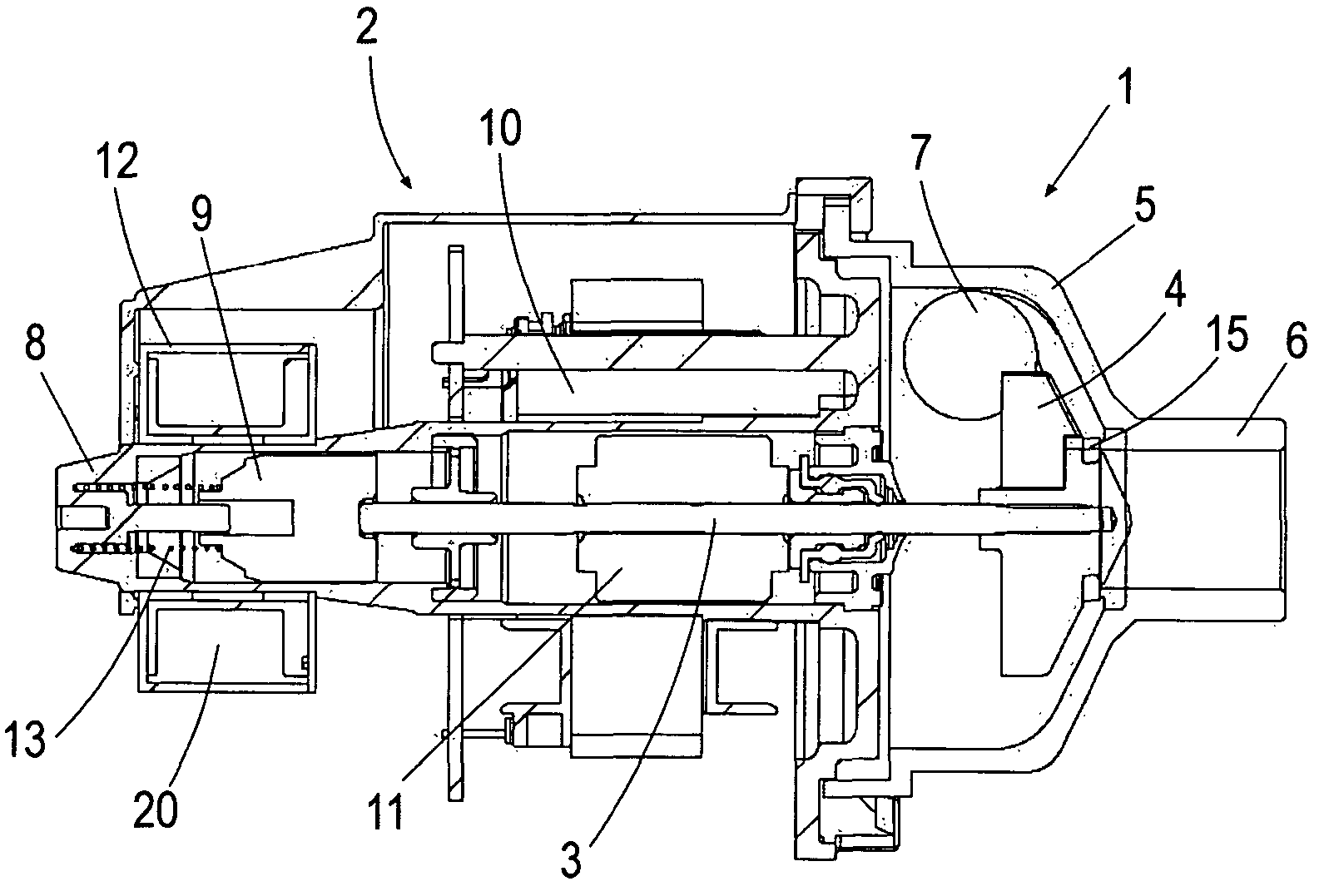
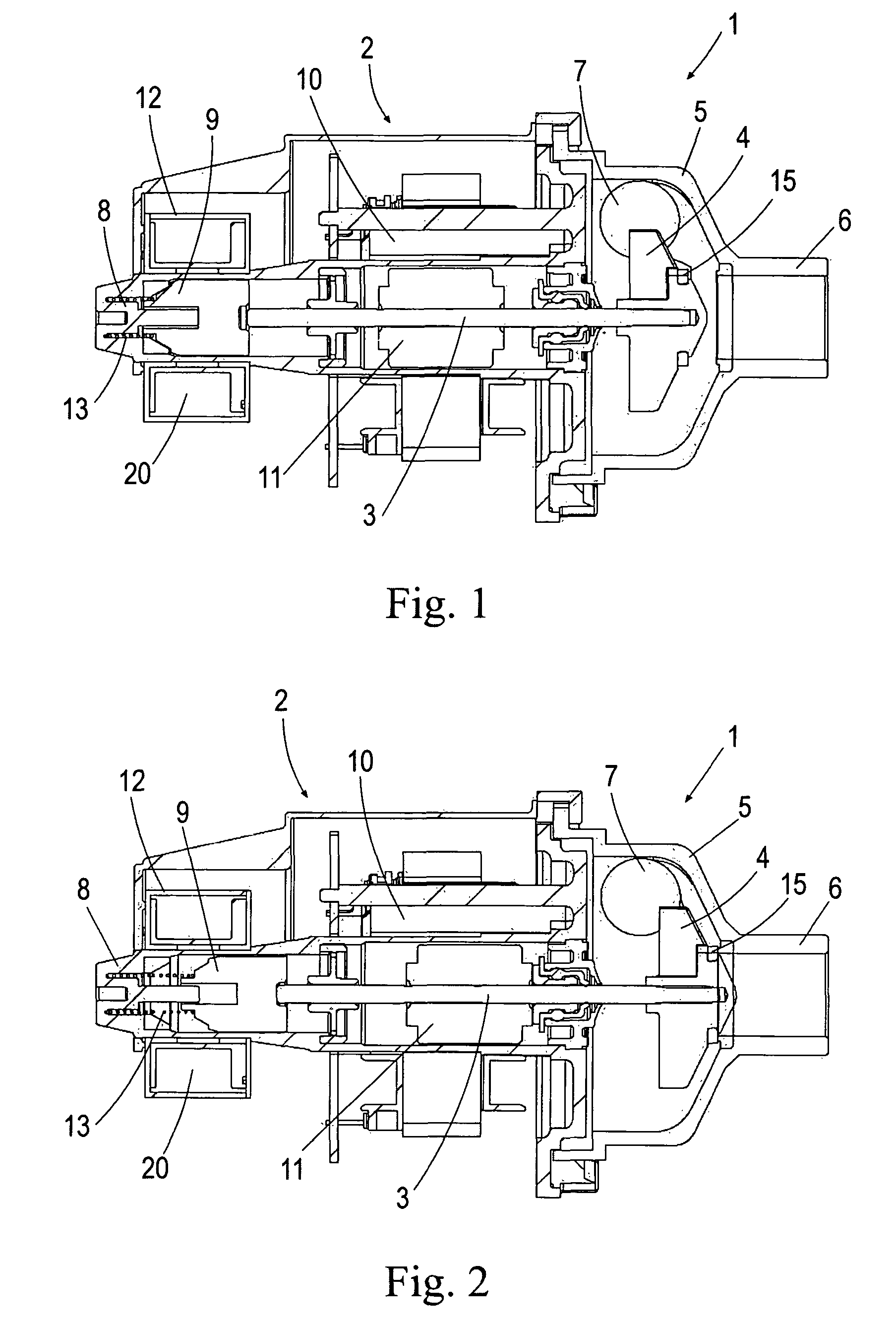
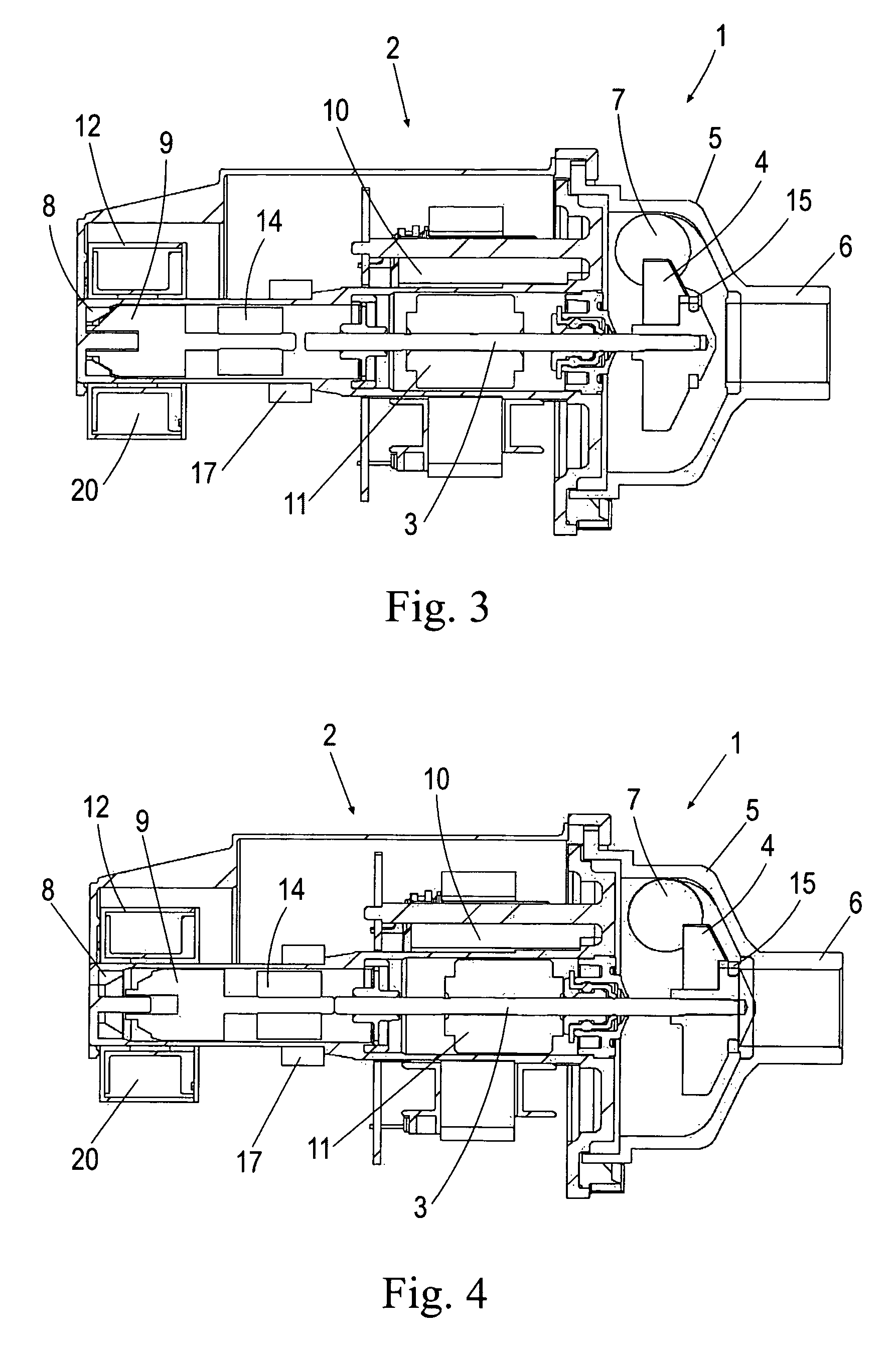
[0023]As the embodiments shown in FIGS. 1 to 4 reveal, the inventive drain pump 1 comprises a motor 2 with a turning shaft 3, an impeller 4 connected to said turning shaft 3, and a hydraulic body 5 in which said impeller 4 is housed. The hydraulic body 5 comprises an inlet conduit 6 which is accessed by the waste water that arrives from the washing chamber of the home appliance, and an outlet conduit 7 from which said waste water is removed to the drain conduit.

[0024]In the two embodiments shown, the motor 2 comprises actuating means to block the inlet conduit 6 when the motor 2 is not being powered and when, therefore, the drain function is not being performed. As a consequence, the motor 2 itself performs the anti-return valve function. When there is no power running to the motor, the blocking means axially move the turning shaft 3 along with the impeller 4, with said impeller 4 blocking the inlet conduit 6 moving, for example, for the first of the embodiments shown (see FIGS. 1 a...


PUM


Abstract

A drain pump for home appliances that includes a motor with a turning shaft, an impeller connected to the turning shaft, and a hydraulic body in which the impeller is housed, the hydraulic body having an inlet conduit and an outlet conduit. The motor includes an actuator to block one of the conduits when the motor is not being powered, the motor itself performing the function of the anti-return valve.

Description

BACKGROUND OF THE INVENTION[0001]The present invention relates to drain pumps for home appliances, in particular for washing machines, dryers and dishwashers.[0002]Drain pumps for home appliances such as washing machines, dryers and dishwashers comprise a motor with a turning shaft, an impeller connected to said turning shaft and a hydraulic body in which said impeller is housed. Said hydraulic body has an inlet conduit from which the waste water from the washing chamber of the home appliance accesses the drain pump, and an outlet conduit from which said waste water is removed to the drain conduit.[0003]In drain pumps the waste water must be prevented from returning in the opposite direction, passing from the drain conduit to the washing chamber of the home appliance, for which purpose anti-return valves are used.[0004]ES 2142714 B1 discloses a water removing system in a washing machine that includes a drain pump that comprises in the outlet conduit a flap valve to perform the anti-...

Claims


Application Information

Patent Timeline
Patent Type & Authority Patents(United States)
IPC IPC(8): F04B35/04
CPCD06F39/085F04D15/0022F04D15/0038F04D29/146F04D29/2261F04D29/042D06F2103/48D06F37/42
Inventor ORUE, RODRIGO
Owner BSH BOSCH & SIEMENS HAUSGERAETE GMBH
Learn More