Device and methods for placing external fixation elements

a technology for fixing elements and devices, applied in the field of methods, systems and devices for orthopedic external fixation, can solve the problems of frame not being properly constructed, frame becoming less adjustable, and difficult to achieve additional reductions

Active Publication Date: 2010-07-20
SMITH & NEPHEW INC
View PDF157 Cites 56 Cited by
  • Summary
  • Abstract
  • Description
  • Claims
  • Application Information

AI Technical Summary

Benefits of technology

[0014]An external fixation system according to one embodiment of this invention allows manipulation of an external fixation component in any plane independent of the number of fixation components used, which is provided by the ability of the fixation component to rotate in multiple planes. Further, an improved fixation component according to one embodiment of this invention provides an external fixation system that does not bind or become constricted when numerous fixation components are used, providing the surgeon a stable system that is adjustable.
[0015]One embodiment of a fixation component according to this invention includes two capture members, a first capture member adapted to capture a first fixation element and a second capture member adapted to capture a second fixation element. The capture members are coupled such that the coupling allows the first capture member and second capture member to rotate about three axes relative to each other and the second capture member to rotate about one axis of the second fixation element and move along that axis. The coupling is adapted to secure the first and second capture members from rotation and secure the second capture member from rotating about and moving along the axis of the second fixation element with a single activation. The second capture member is adapted to capture the second fixation element by snapping onto the second element from substantially perpendicular to the longitudinal axis of the second element.
[0016]A drill guide according to an exemplary embodiment of this invention allows for optimal placement of fixation elements into a patient's bone. According to one embodiment, a collar frame includes a collar adapted to receive a bar of an external fixation system such that the collar may be moved linearly or rotationally about the bar. A guide frame, including a bore through which a fixation element, such as a pin or wire, of the external fixation system may be inserted, is coupled to the collar frame such that the guide frame and the collar frame may rotate about at least one axis relative to each other. A drill, drill bit, depth gauge, or tissue sleeve may also be inserted through the bore of the guide frame. In one embodiment, the guide frame and collar frame may rotate about three axes relative to each other.
[0017]In one embodiment, the bore of a guide frame may receive a tissue or drill sleeve that includes a channel through which a fixation element may be inserted. The tissue sleeve may assist in pushing soft tissue away from the end of a fixation element as the fixation element is placed into the patient's bone. In one embodiment, a drill guide is designed to mimic the positioning and rotational freedom of an embodiment of a fixation component according to the invention.

Problems solved by technology

As additional fixation components are added to the system in different planes, the frame become less adjustable.
Thus, additional reduction is difficult to achieve and requires reestablishment of optimal position.
For example, if the pins or wires are angled incorrectly, the frame cannot be properly constructed.
This requirement limits the system, as the positioning of each clamp is inhibited.
Similar to other current designs, this design becomes substandard when several fixation components are used because it becomes constrained.
In addition, current designs use compression to hold the bar or pin in place, and may allow dislodgement of the pin or bar upon application of a great amount of pressure to the system when being placed.
This limits position of both the pin and the fixation component and is a significant disadvantage because the pin may be placed in a non-optimal position.
These specialized systems do not cooperate with general external fixation systems, and must be used separately.

Method used


Image

  • Device and methods for placing external fixation elements
  • Device and methods for placing external fixation elements
  • Device and methods for placing external fixation elements

Examples


Embodiment Construction

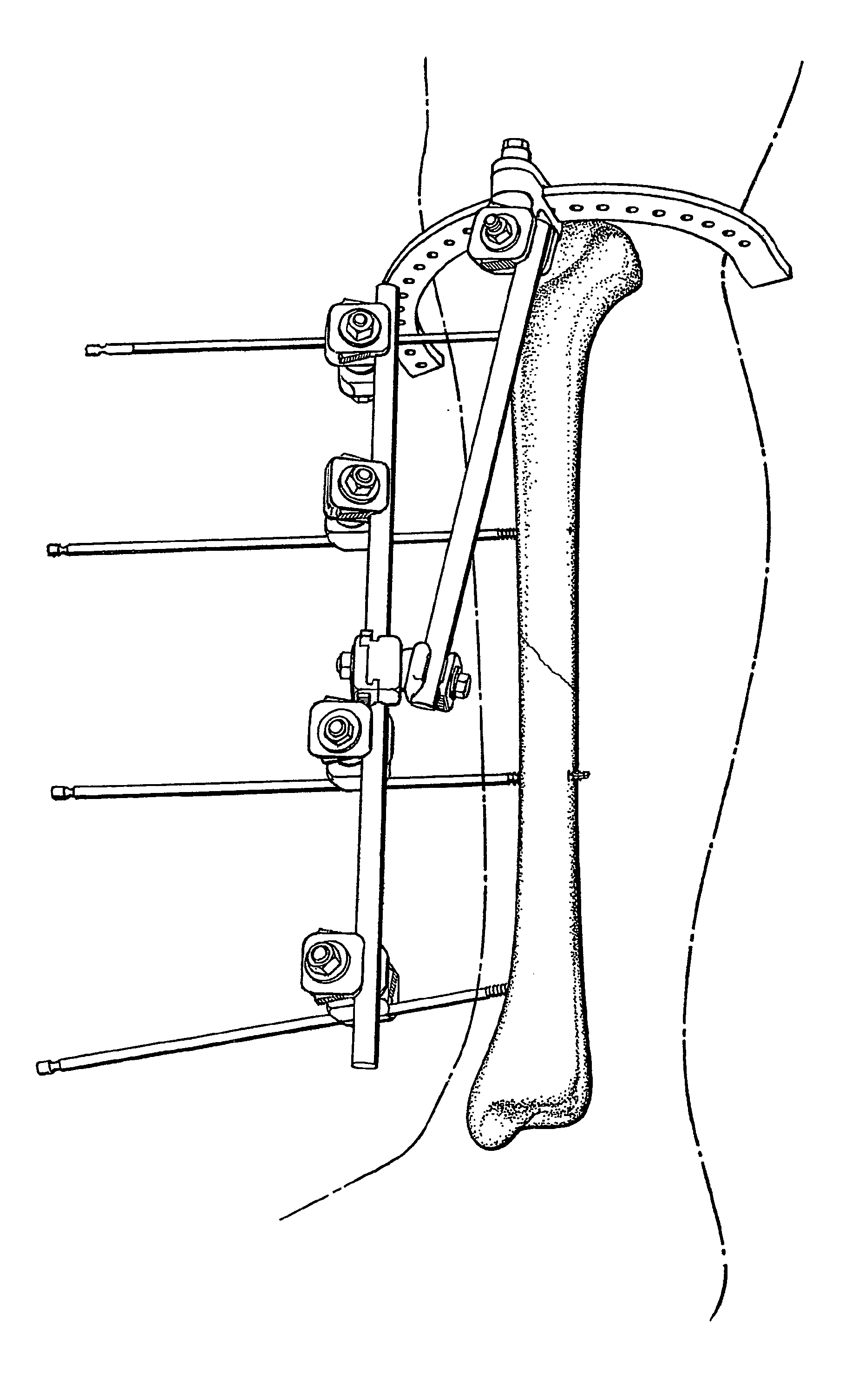
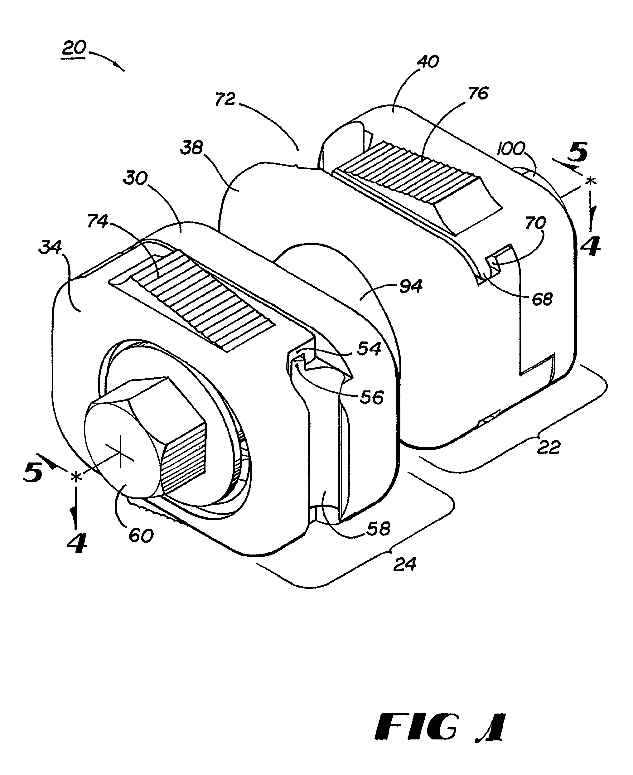
[0036]Methods, systems, and devices according to this invention seek to provide improved external fixation, including an improved fixation component allowing an increase in freedom of rotation, independent locking of capture members, a more stable, yet more flexible frame, and cooperation with specialized fixation systems. External fixation systems according to embodiments of this invention may include fixation components designed to retain one or more fixation elements. In general, the fixation components either connect a bar to a bar; a bar to a pin; a bar to a wire; or a bar to a circumferential or half ring. Each fixation component generally includes two capture members, and each capture member includes a base and a head. Methods, systems, and devices according to this invention also provide drill guides for optimal placement of fixation elements into a patient's bone, as discussed in further detail below.

[0037]One embodiment of a fixation component according to this invention i...


PUM


Abstract

Methods, systems, and devices according to this invention provide drill guides for optimal placement of fixation elements, such as half pins, into a patient's bone. According to one embodiment, a collar frame (202) with a collar adapted (204) to receive a bar (270) of an orthopedic external fixation system such that the collar may be moved linearly or rotationally about the bar is coupled to a guide frame (224) including a bore (232) through which a fixation element (266) of the external fixation system may be inserted. The coupling between the collar frame and the guide frame allows for them to rotate about at least one axis relative to each other. In one embodiment, the collar frame and the guide frame may rotate about three axes relative to each other.

Description

CROSS REFERENCE TO RELATED APPLICATIONS[0001]This application is the U.S. national phase of International Application No. PCT / US03 / 18067 filed on Jun. 10, 2003 and published in English as International Publication No. WO 03 / 105704 A1 on Dec. 24, 2003 which application claims priority to U.S. application Ser. No. 10 / 172,654, filed Jun. 14, 2002, now pending, entitled “Devices, Systems, and Methods for Placing and Positioning Fixation Elements in External Fixation Systems,” the entire contents of which are hereby incorporated by reference.FIELD OF THE INVENTION[0002]This invention relates generally to methods, systems, and devices for orthopedic external fixation and more particularly to methods, systems, and devices for use with external fixation systems for placing fixation elements, such as half pins, in a patient's bone.BACKGROUND OF THE INVENTION[0003]Surgeons use external fixation systems regularly to treat certain bone-related injuries or conditions, such as acute fractures of ...

Claims


Application Information

Patent Timeline
Patent Type & Authority Patents(United States)
IPC IPC(8): A61B17/58A61F2/00A61B17/17A61B17/64A61B19/00
CPCA61B17/6466A61B17/171A61B19/203A61B2019/267A61B2019/5289A61B2019/5483A61B2090/3983A61B90/57A61B2090/364A61B90/14
Inventor FERRANTE, JOSEPHAUSTIN, GENE EDWARDJAMES, ANTHONY
Owner SMITH & NEPHEW INC
Why Eureka
Try Eureka