
Device for connecting a screw to a support plate

a technology for connecting devices and supporting plates, which is applied in the field of devices for connecting screws and supporting plates, can solve the problems of screw installation, reducing the distance between plates and bones, and thus unable to draw back bone fragments, and achieves good resistance to pulling out, easy installation and removal

Active Publication Date: 2010-07-20
STRYKER EURO OPERATIONS HLDG LLC
View PDF30 Cites 22 Cited by
  • Summary
  • Abstract
  • Description
  • Claims
  • Application Information

AI Technical Summary

Benefits of technology

The present invention proposes a device for solidly connecting a part, such as a bone plate, to a support, such as a bone. The device allows for easy installation and removal of the assembly while offering good resistance to pull out and to the stresses exerted parallel to the plate. The invention includes a threaded rod or screw passing through a hole or aperture in the plate, with a ring for clamping the head of the screw around the screw to immobilize it. The method involves introducing the screw into the ring, then driving the screw to its final position, and then rotating the ring to constrict it around the screw to secure it in place. The technical effects of the invention include optimizing the connection between the plate and the support, simplifying the installation process, and providing good resistance to pull out and stresses.

Problems solved by technology

One such system that achieves locking by wedging of a tapered thread into a tapped tapered hole has, as a problem, the fact that as the screw is engaged simultaneously in the plate and in the bone, the possible distance between plate and bone may no longer be reduced.
Drawing back a bone fragment is thus impossible.
Because of this, the distance between the plate and the bone must be set before the installation of the screw, which is sometimes difficult.
Moreover, existing devices do not allow the plate and the support, such as the bone, to be brought together optimally without impairing coaxiality between axis of the plate and axis of the internal thread.
Moreover, risks from detachment of metal particles cannot be ruled out.

Method used


Image

  • Device for connecting a screw to a support plate
  • Device for connecting a screw to a support plate
  • Device for connecting a screw to a support plate

Examples


Embodiment Construction

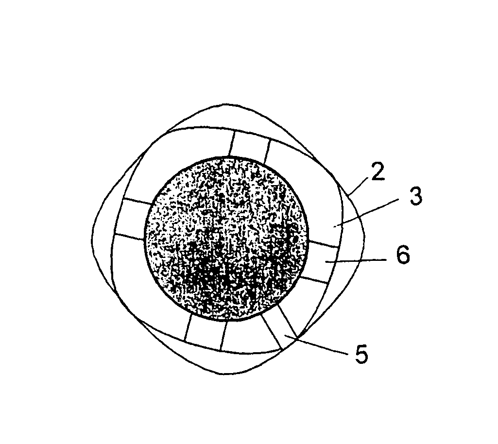
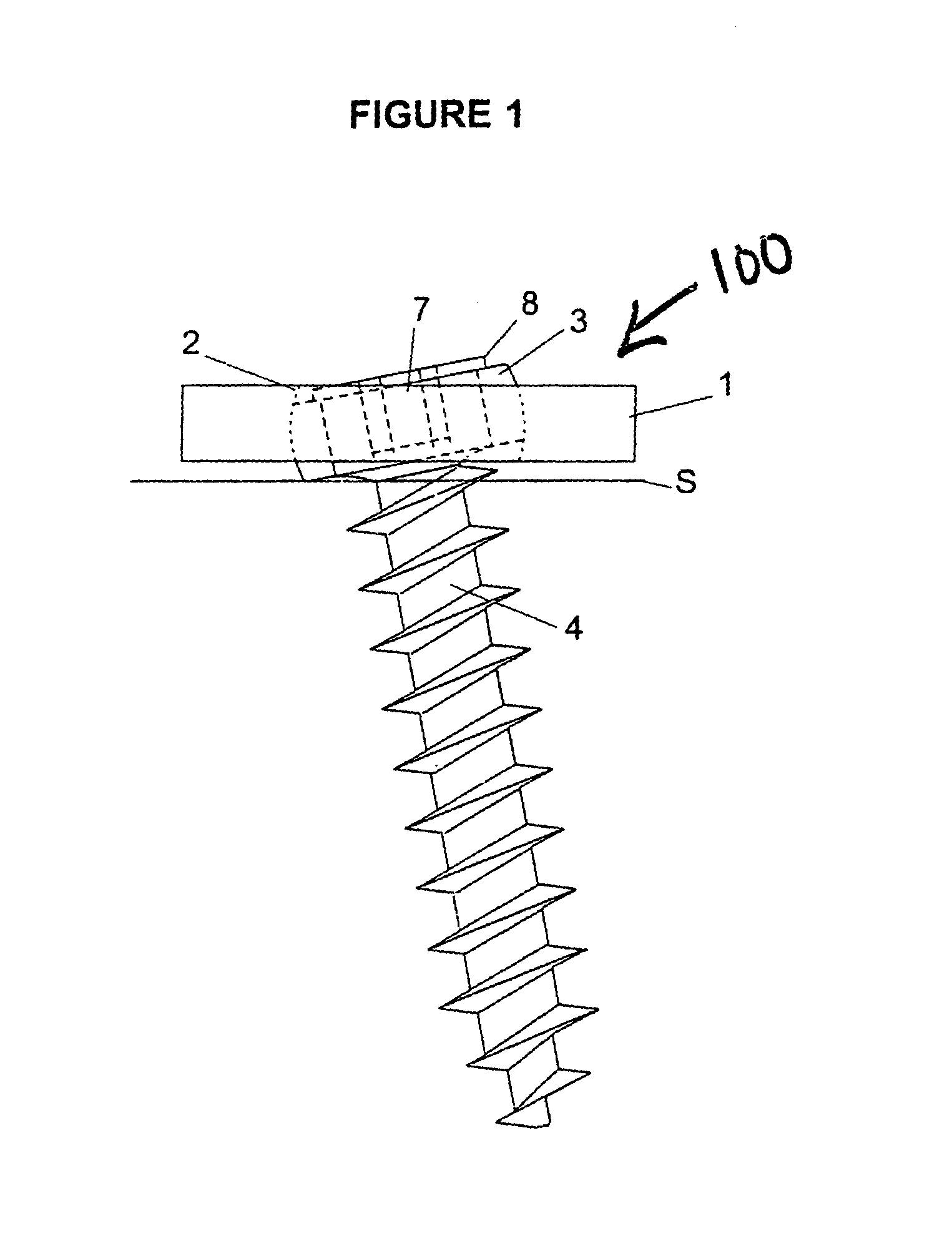
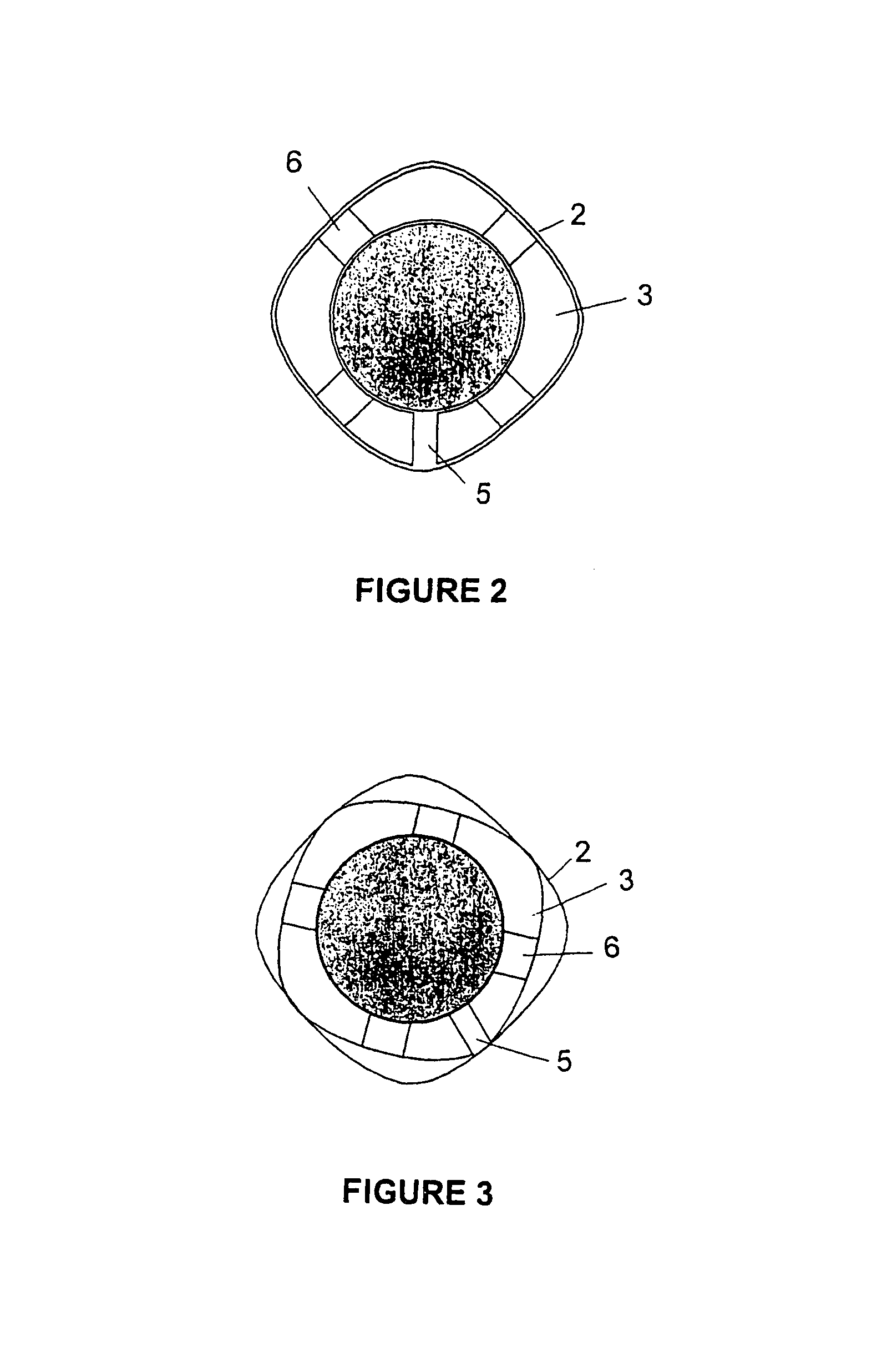
[0025]Referring to FIG. 1 there is shown the connection device of the present invention generally denoted as 100, comprising a part 1 able to be solidly connected on a support S using at least one fixing element 4. As mentioned above, this device is more specifically intended for the medical field. In this case, the part 1 is an implant generally taking the form of a plate and the support S is at least one bone. Fixing the element 4 for its part comprises a rod or screw threaded over at least part of its length. Rod or screw 4, which ensures the solid connection of the part 1 on the support S, passes through a hole 2 in the plate or part 1 and is anchored on the support S. The hole 2 of this part 1 is provided with a ring 3 traversed by the fixing element 4. The present invention, ring 3 can be constricted at the time of its rotational drive into the hole 2, this constriction of the inner diameter of ring 3 ensuring, generally by cooperation with the head or end part of the thread o...


PUM


Abstract

The invention relates to a device which is used for solidly connecting a part such as a plate to an underlying support using at least one fixing element such as a screw. According to the invention, said fixing element takes the form of a threaded rod a screw which passes through a hole housing a ring belonging to the part, such that it is screwed into the support material. The inventive device is characterized in that the above-mentioned ring is a constriction ring comprising a non-circular outer profile which co-operates with the non-circular inner profile of the hole, which is in the part. In this way, when the ring is rotated in the hole and wedged in place therein, it is constricted, thereby blocking the threaded rod against movement with respect to the plate.

Description

CROSS-REFERENCE TO RELATED APPLICATIONS[0001]This application is a continuation-in-part of WO 2004 / 028334 A2 filed Sep. 22, 2003, designating the United States, which claimed priority of FR 02 / 11802 filed Sep. 24, 2002.BACKGROUND OF THE INVENTION[0002]The present invention relates to a device for solidly connecting a part, such as an osteosynthesis plate, to a support, such as a bone mass. The device has at least one fixing component taking the form of a threaded rod or screw passing through an aperture or hole in the plate. The hole includes a ring belonging to the plate such that it can lock the screw after it is screwed into the support material. The plate can be in the form of a spherical acetabular cup shell for contacting the natural acetabulum.[0003]Screw-and-plate osteosynthesis systems must allow immobilizing one or more bone fragments in reference to others. It is known to use spherical-head screws cooperating with a spherical housing housed in a plate and bringing the pla...

Claims


Application Information

Patent Timeline
Patent Type & Authority Patents(United States)
IPC IPC(8): A61B17/80
CPCA61B17/8047
Inventor PORCHER, ROBERT
Owner STRYKER EURO OPERATIONS HLDG LLC
Learn More