Surface-mount type crystal oscillator

a crystal oscillator and surface mount technology, applied in the field of surface mount crystal oscillators, can solve the problems of change in oscillation frequency, inability to provide various communication terminals on the outer surface of the container body, etc., and achieve the effect of small crystal oscillator height, easy operation of flip-chip bonding, and large planar dimension of the ic chip which is mounted

Inactive Publication Date: 2010-07-20
NIHON DEMPA KOGYO CO LTD
View PDF7 Cites 15 Cited by
  • Summary
  • Abstract
  • Description
  • Claims
  • Application Information

AI Technical Summary

Benefits of technology

[0017]With such a configuration, the crystal blank and the IC chip are disposed in the container body side by side in the horizontal direction, and therefore, the height of the crystal oscillator is kept small. Further, the IC chip is disposed outside the recess, and thereby, the operation of flip-chip bonding can be easily performed. The size of the IC chip is not limited by the frame wall, and therefore, even an IC chip with a relatively large planar outer shape size which is used in a temperature compensated crystal oscillator can be mounted on the container body. The crystal inspection terminal is provided on the flat part, and therefore, when the crystal oscillator is surface-mounted on the wiring board, occurrence of electrical coupling between the wiring pattern of the wiring board and the crystal inspection terminal can be suppressed.
[0018]In the present invention, a protection resin is preferably injected between a circuit formation plane of the IC chip and the one principal surface of the bottom wall. At this time, a jetty, which is lower in height than a diameter of a bump for use in the flip-chip bonding and is narrower in width than frame width of the frame wall, may be provided along an outer perimeter of the flat part, and the protection resin may be injected into the flat part in a region surrounded by the jetty. By providing the jetty, the protection resin can be prevented from flowing out from the perimeter of the flat part at the time of injection of the liquid protection resin without using a special jig or the like. The jetty, which is constituted of, for example, alumina or the like and can be provided by a printing method, can be formed by fine width, and therefore, the planar dimension of the IC chip which is mounted can be made large. Further, the height of the jetty is lower than the diameter of the bump, and therefore, the operation of flip-chip bonding can be easily performed

Problems solved by technology

However, the surface-mount type crystal oscillator of the aforementioned configuration has the problem of being incapable of providing various communication terminals on an outer surface of the container body, though the height dimension can be made small.
However, when the communication terminal is provided like this, if the communication terminal is a crystal inspection terminal, the wiring pattern on the wiring board and the crystal inspection terminal are close to each other and both of them are electrically coupled, and may cause a change in oscillation frequency when the crystal oscillator is mounted on the wiring board.
Since IC chip 3 is also housed in the recess of container body 1, there is the problem that IC chip 3 needs to be small by the frame width of frame wall 1b configuring the recess as compared with the outside dimension of container body 1, and IC chip 3 of a large planar dimension cannot be used.

Method used


Image

  • Surface-mount type crystal oscillator
  • Surface-mount type crystal oscillator
  • Surface-mount type crystal oscillator

Examples


Embodiment Construction

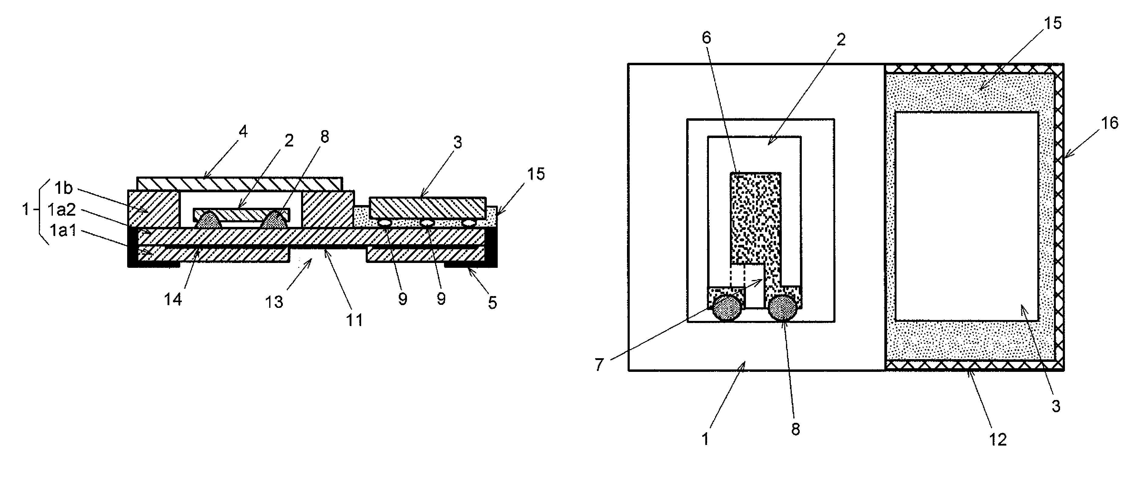
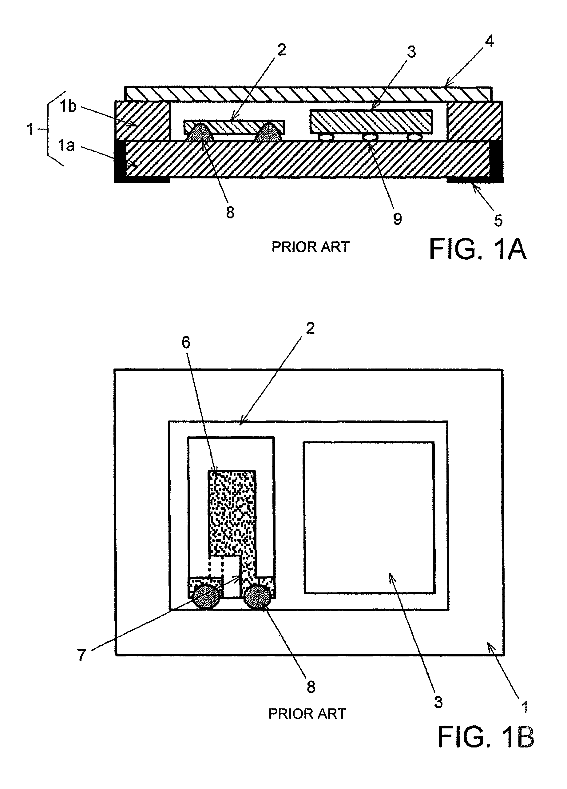
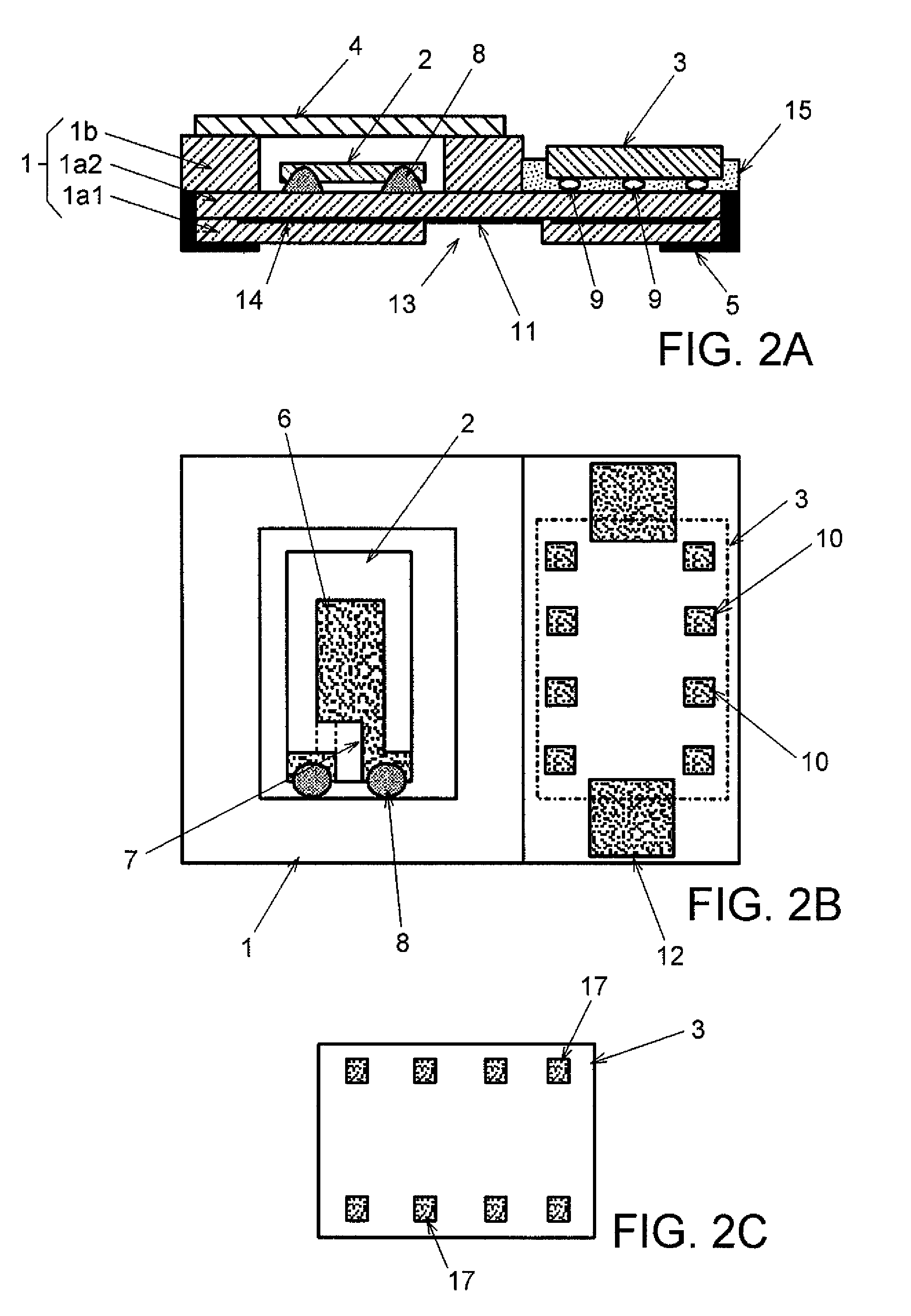
[0025]In FIGS. 2A to 2C showing a surface-mount type crystal oscillator according to a first embodiment of the present invention, the same components in FIGS. 1A and 1B are assigned with the same reference numerals, and the redundant description is not repeated.

[0026]In the crystal oscillator of the first embodiment, quartz crystal blank 2 and IC chip 3 are disposed on one principal surface of container body 1 side by side in the horizontal direction Container body 1 is configured by laminated ceramics constituted of planar bottom wall 1a and frame-shaped frame wall 1b provided on bottom wall 1a as in the above described one. Bottom wall 1a has a laminated structure of lower layer 1al at the lower side and upper layer 1a2 at the upper side as illustrated in FIG. 2A. In the present embodiment, the outer perimeter dimension of frame wall 1b is set at about a half of the outer perimeter dimension of bottom wall 1a, and frame wall 1b is provided in, for example, only in a region of a le...


PUM


Abstract

A surface-mount type crystal oscillator has: a container body having a bottom wall and a frame wall having an opening and provided on one principal surface of the bottom wall; a quartz crystal blank hermetically encapsulated in a recess of the container body, which is formed by the opening of the frame wall; and an IC chip on which an oscillating circuit using the crystal blank is integrated. A region which is a region on the one principal surface of the bottom wall and other than formation regions of the frame wall and the recess is made a flat part, and the IC chip is fixed to the one principal surface of the bottom wall by flip-chip bonding, in the flat part. A crystal inspection terminal electrically connected to the crystal blank is provided on a surface of the flat part.

Description

BACKGROUND OF THE INVENTION[0001]1. Field of the Invention[0002]The present invention relates to a surface-mount type crystal oscillator, and particularly relates to a surface-mount type crystal oscillator capable of suppressing height from a wiring board to be low when surface-mounted on the wiring board.[0003]2. Description of the Related Arts[0004]Surface-mount type crystal oscillators each configured by integrating a quartz crystal blank and an IC chip which includes an oscillating circuit using the crystal blank are used as reference sources for frequency and time by being incorporated in portable electronic devices typified by, for example, portable telephones because of its compactness and light weight. Depending on the configurations of the devices in which the crystal oscillators are used, the surface-mount type crystal oscillators are sometimes required to be especially small in thickness, that is, height from the surfaces of the wiring boards, when they are surface-mounte...

Claims


Application Information

Patent Timeline
Patent Type & Authority Patents(United States)
IPC IPC(8): H03B1/00
CPCH03H9/0542H03H9/1021
Inventor MORIYA, KOUICHI
Owner NIHON DEMPA KOGYO CO LTD
Why Eureka
Try Eureka