Electromagnetic switch for use in starter
a technology of electromagnetic switch and starter, which is applied in the direction of engine starter, machine/engine, relay, etc., can solve the problems of difficult to employ the shape of a waterproof coupler, difficult to suppress the b>50/b> terminal from vibrating, etc., and achieves high vibration resistance and small parts count
- Summary
- Abstract
- Description
- Claims
- Application Information
AI Technical Summary
Benefits of technology
Problems solved by technology
Method used
Image

Examples
first embodiment
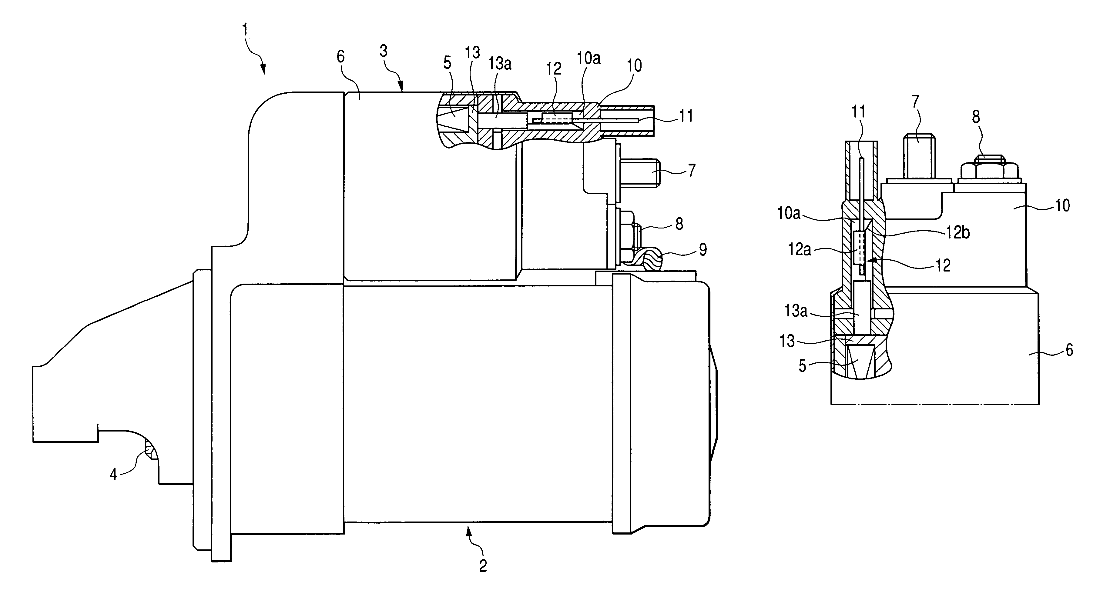
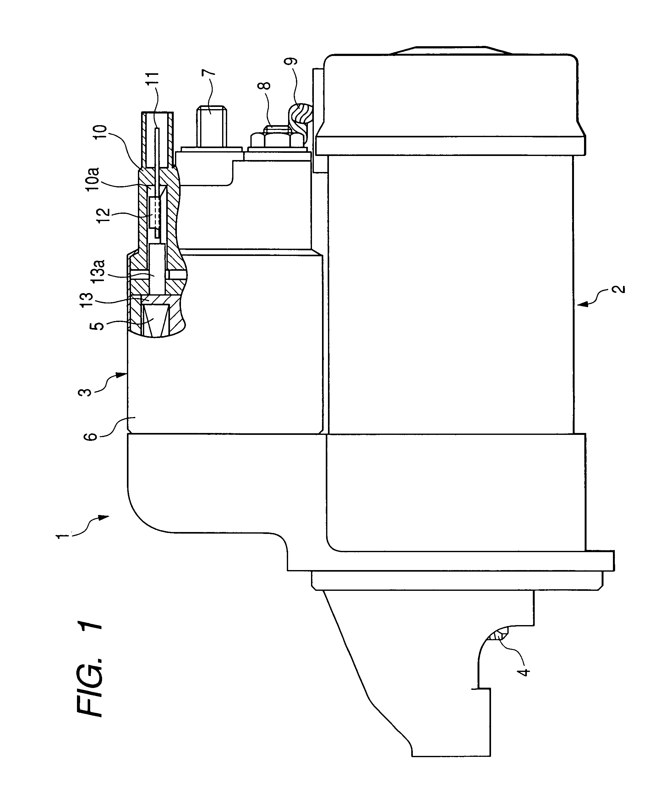
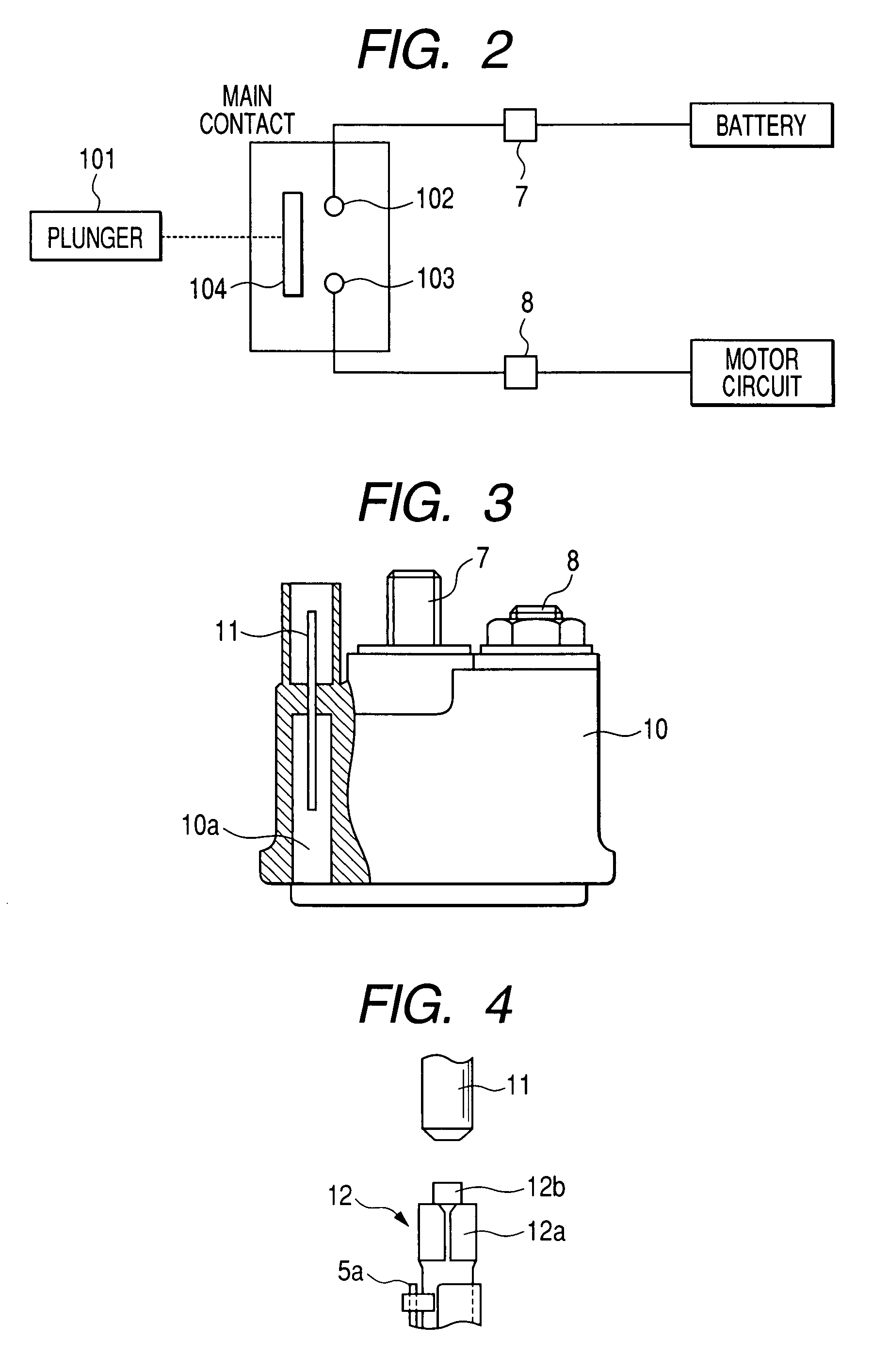
[0047]FIG. 1 is a diagram showing cross-sectional views of major parts of an electromagnetic switch 3 according to a first embodiment of the invention, which is included in a starter 1. The starter 1 includes a motor 2 for generating a torque to start a vehicle engine, the electromagnetic switch 3 operating to open and close a main contact (to be explained later) provided in an energizing circuit of the motor 2 (referred to as “motor circuit” hereinafter), and a pinion gear 4 to which the torque generated by the motor 2 is transmitted to cause the pinion gear to rotate. The starter 1 operates to start the vehicle engine by transmitting the torque generated by the motor 2 to a ring gear (not shown) of the vehicle engine through the pinion gear 4. The motor 2 is a DC motor that generates the torque at its armature (not shown) when the main contact is closed to supply electric power from a battery (not shown) to the motor 2.
[0048]The electromagnetic switch 3 includes an excitation coil...
second embodiment
[0057]FIG. 7A is a side view of the mold cover 10 including a partial cross-sectional view of the mold cover 10 of the electromagnetic switch according to a second embodiment of the invention, and FIG. 7B is an axial plan view of this mold cover 10. The second embodiment is an example in which the 50 terminal 11 insert-molded in the mold cover 10 is bent within the mold cover 10. As shown in FIG. 7A, the 50 terminal 11 is bent so as to have a section extending in the radial direction of the mold cover 10 between one end portion thereof projecting outside from the mold cover 10 and the other end portion projecting inside the mold cover 10. Accordingly, in the second embodiment, the one end portion of the 50 terminal 11 is led outside the outer periphery of the mold cover 10 as shown in FIG. 7B. According to the second embodiment, the position to which the one end portion of the 50 terminal 11 is led outside the mold cover 10 can be set arbitrarily without being affected by the positi...
third embodiment
[0058]In the above described first and second embodiments, the 50 terminal 11 insert-molded in the mold cover 10 is a male terminal, and the connection terminal 12 fixed to the coil bobbin 13 of the excitation coil 5 is a female terminal, however it may be vice versa. That is, as shown in FIG. 7, it is possible that the 50 terminal 11 is a female terminal having a fitting section as shown in FIG. 8, and the connection terminal 12 is a male terminal having a plate-like shape.
PUM
 Abstract
Description
Claims
Application Information
 - Generate Ideas
- Intellectual Property
- Life Sciences
- Materials
- Tech Scout
- Unparalleled Data Quality
- Higher Quality Content
- 60% Fewer Hallucinations
Browse by: Latest US Patents, China's latest patents, Technical Efficacy Thesaurus, Application Domain, Technology Topic, Popular Technical Reports.
© 2025 PatSnap. All rights reserved.Legal|Privacy policy|Modern Slavery Act Transparency Statement|Sitemap|About US| Contact US: help@patsnap.com