
Driving force distributing device

Active Publication Date: 2016-11-10
HONDA MOTOR CO LTD
View PDF3 Cites 2 Cited by
  • Summary
  • Abstract
  • Description
  • Claims
  • Application Information

AI Technical Summary

Benefits of technology

The driving force distributing device described in this patent allows for independent control of the flow rate of hydraulic fluid to two hydraulic clutches. This means that individual control of the driving force to each driving wheel is possible in a simple and compact device with minimal parts.

Problems solved by technology

However, in this configuration, each of the two hydraulic clutches requires a pair of oil pump and rear solenoid valve, possibly leading to increase in size, weight and cost of the structure of the hydraulic pressure supply device.
Therefore, in this case also, having a large parts count, the hydraulic pressure supply device might increase in size, weight and cost of the structure.

Method used


Image

  • Driving force distributing device
  • Driving force distributing device
  • Driving force distributing device

Examples


Embodiment Construction

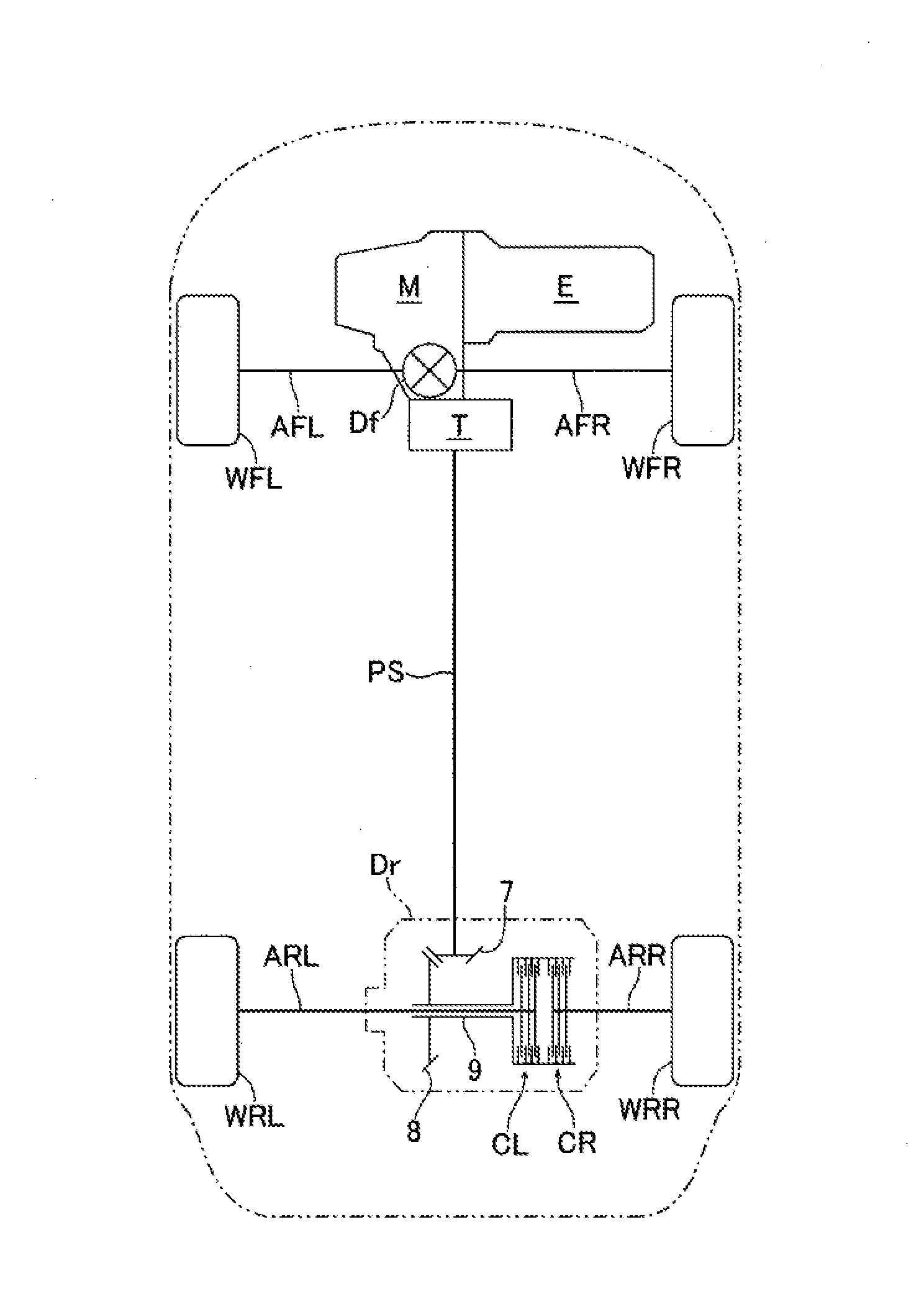
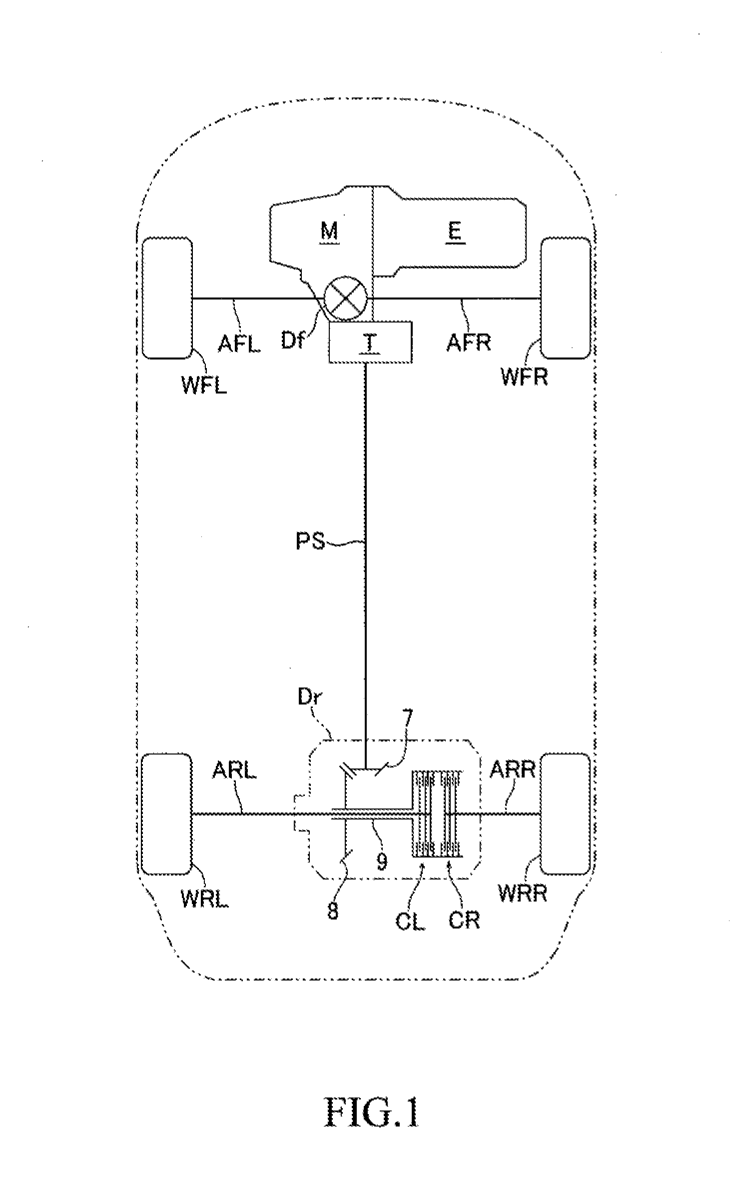
[0025]Hereinafter, an embodiment of the present invention will be described in detail with reference to the appending drawings. FIG. 1 is a view illustrating a driving power transmission route of a four-wheel drive vehicle according to one embodiment of the present invention. The vehicle shown in FIG. 1 is a four-wheel drive vehicle based on a front engine / front wheel drive vehicle and includes front wheels WFL, WFR serving as main driving wheels and rear wheels WRL, WRR serving as auxiliary driving wheels. To the front wheels WFL, WFR, driving force from an engine (driving source) E is transmitted via a transmission M, a front differential Df and left and right axles AFL, AFR. To the rear wheels WRL, WRR, part of driving force of the front wheels WFL, WFR is transmitted via a transfer T, a propeller shaft PS, a rear differential Dr and left and right axles ARL, ARR.

[0026]The rear differential Dr includes a left clutch (first hydraulic clutch) CL and a right clutch (second hydraulic...


PUM


Abstract

A driving force distributing device includes a single pump for supplying control hydraulic pressure to each of first and second hydraulic clutches, an electric motor for driving the pump, a flow rate variable mechanism for changing a ratio of flow rate of hydraulic fluid supplied to each of the first and second hydraulic clutches and a controlling means for controlling the electric motor and the flow rate variable mechanism. The driving force distributing device can variably control a flow rate of hydraulic fluid supplied to first and second hydraulic clutches based on changing a ratio of flow rate of hydraulic fluid supplied to the first and second hydraulic clutches in the flow rate variable mechanism and a control of changing rotational speed of the pump using the motor.

Description

TECHNICAL FIELD[0001]The present invention relates to a driving force distributing device for distributing driving force from a driving source to each of a pair of driving wheels.BACKGROUND ART[0002]As a conventional art, as disclosed in Patent Document 1, a driving force distributing device configured in a manner that a left hydraulic clutch and a right hydraulic clutch are arranged respectively on left and right sides of a hypoid gear or a bevel gear coupled to a rear end of a propeller shaft for distributing driving force (so-called “torque distribution”) transmitted from a driving source such as an engine to each of a pair of left and right wheels (left and right rear wheels) is known to be available.[0003]The driving force distributing device disclosed in Patent Document 1 is configured to regulate pressure of hydraulic fluid discharged from an oil pump driven by an electric motor using a linear solenoid valve (pressure regulating valve), and due to this hydraulic pressure of h...

Claims


Application Information

Patent Timeline
IPC IPC(8): B60K23/08F16H48/32F04C14/18F04C2/344F04C15/06F16D25/10F16D48/02
CPCB60K23/0808F16D25/10F16H48/32F16D25/14F04C2/3448F04C2240/30F04C14/18B60K17/35B60K2023/0833F16H48/22F16D2121/04F04C15/06F04C2/3446F04C14/223F04C2270/0525F16D25/0638F16D48/0206
Inventor TSUCHIHASHI, MAKOTOFUJINUMA, SACHI
Owner HONDA MOTOR CO LTD
Features
  • Generate Ideas
  • Intellectual Property
  • Life Sciences
  • Materials
  • Tech Scout
  • Unparalleled Data Quality
  • Higher Quality Content
  • 60% Fewer Hallucinations
Learn More