
Wireless bicycle communication device

a communication device and bicycle technology, applied in the direction of cycle control system, optical signal, cycle equipment, etc., can solve the problems of wind resistance or drag, creating additional drag, and not desirable hands from the grip portion of the handlebar, so as to reduce the wind resistance of the bicycle

Active Publication Date: 2010-07-20
SHIMANO INC
View PDF15 Cites 45 Cited by
  • Summary
  • Abstract
  • Description
  • Claims
  • Application Information

AI Technical Summary

Benefits of technology

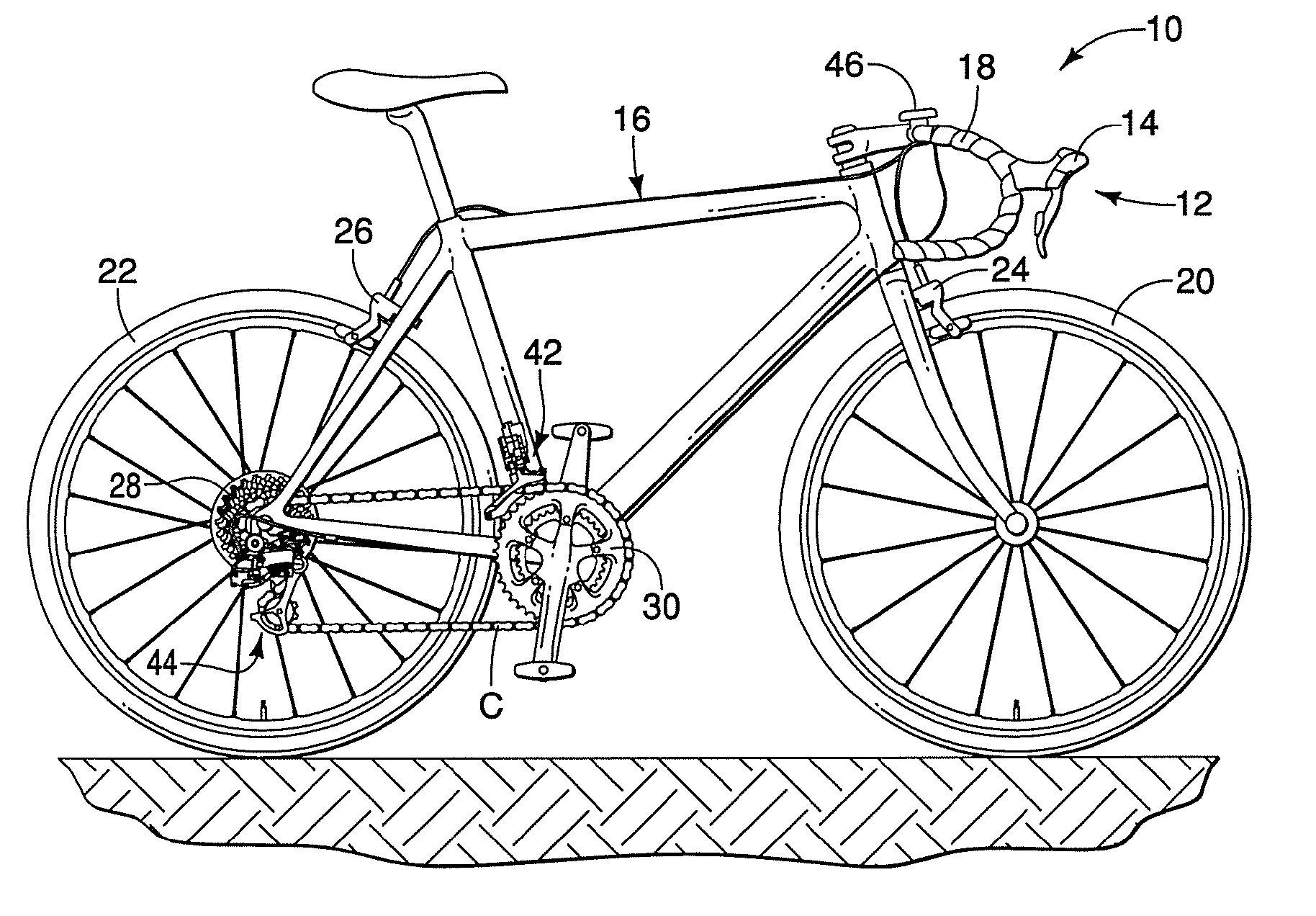
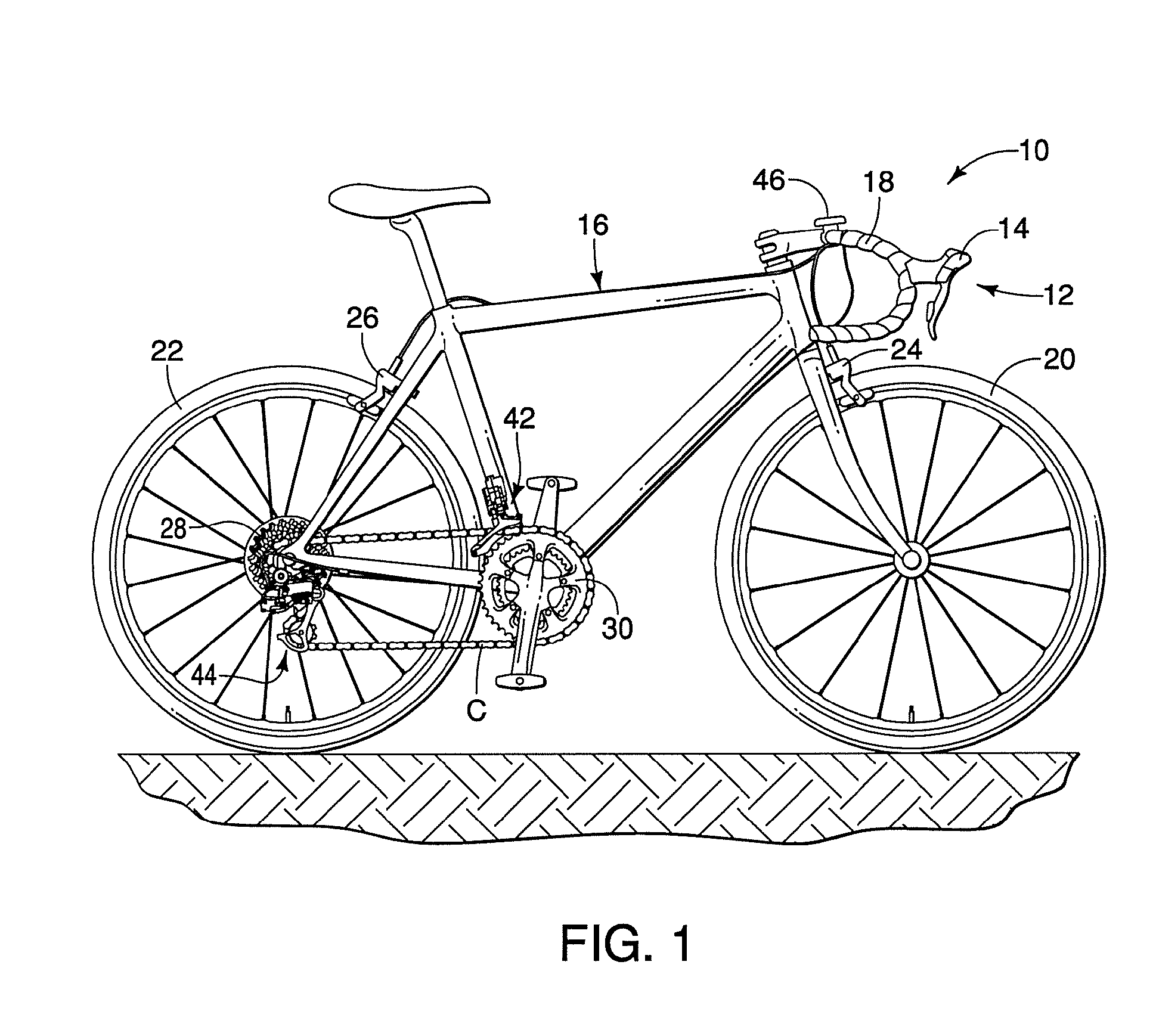
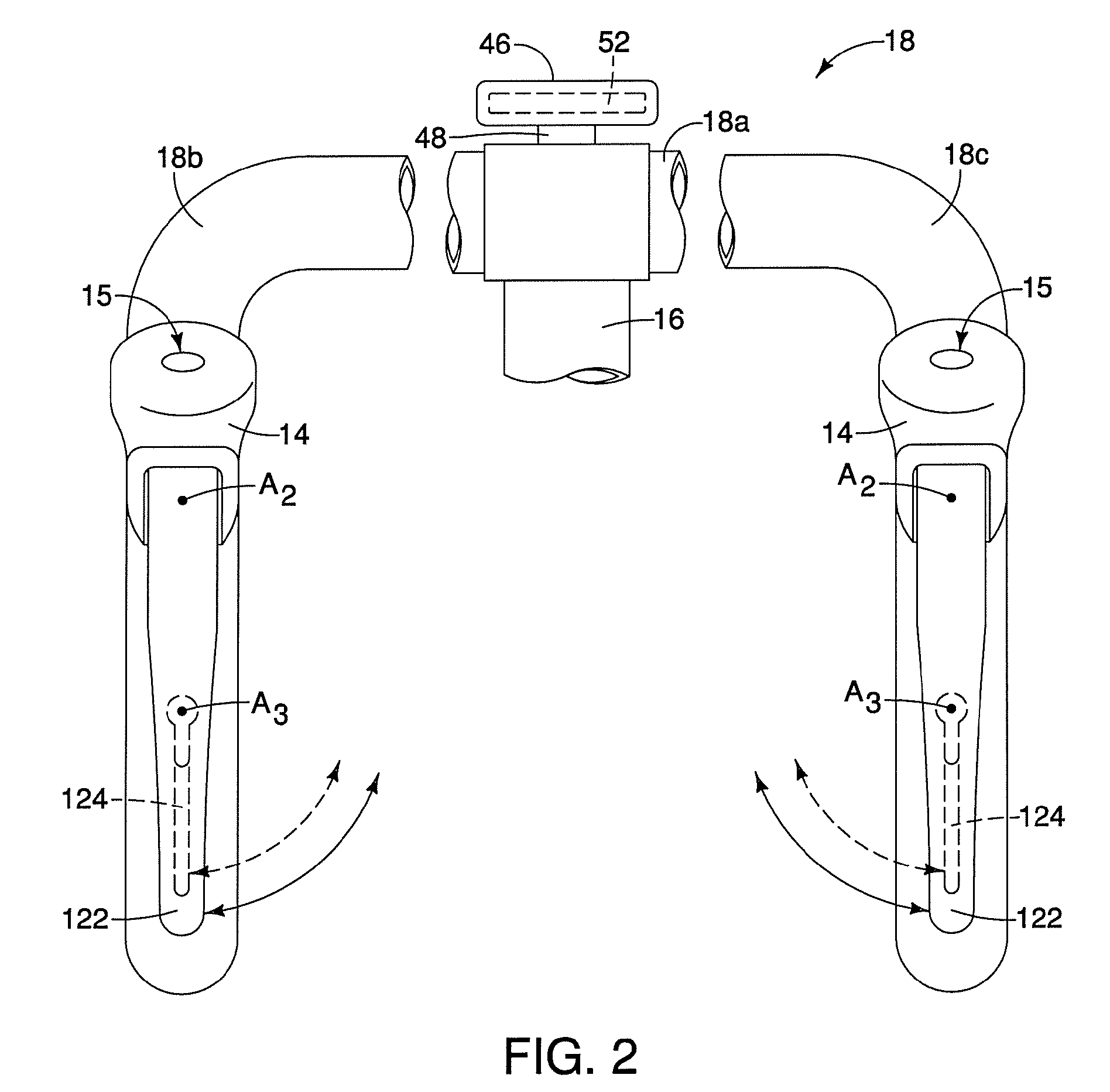
The present invention is a wireless communication device for bicycles that aims to reduce wind resistance, eliminate exposed wires, and provide a more seamless appearance. The device includes a bracket, an electronic switch, an antenna, a wiring assembly, and a radio communication unit. The bracket attaches to the bicycle frame, the electronic switch is connected to the bracket, and the antenna is supported by the bracket. The wiring assembly connects the antenna to the radio communication unit, which is housed within the bracket and has a connector for easy installation. The radio communication unit processes the switching signals from the electronic switch and sends out radio signals through the antenna. Overall, the invention provides a seamless and efficient communication system for bicycles.

Problems solved by technology

During a race, moving the hands from the grip portion of the handlebar is not desirable.
Further, each component installed on the exterior of a bicycle frame has the potential to create wind resistance or drag.
Simple components, such as wires and cables can contribute to drag when cycling at high speeds.
However, wires extending from a shifter mounted to a handlebar of the bicycle frame are still exposed, thus contributing to wind resistance.
Display units having a remote switch also typically include a wire extending between the remote switch and the display unit, thus creating additional drag.

Method used


Image

  • Wireless bicycle communication device
  • Wireless bicycle communication device
  • Wireless bicycle communication device

Examples


second embodiment

[0088]Referring now to FIG. 24-26, a wireless communication device 214 in accordance with a second embodiment will now be explained. In view of the similarity between the first and second embodiments, the parts of the second embodiment that are identical to the parts of the first embodiment will be given the same reference numerals as the parts of the first embodiment. Moreover, the descriptions of the parts of the second embodiment that are identical to the parts of the first embodiment may be omitted for the sake of brevity.

[0089]In the second embodiment, the wireless communication device 214 includes all the features of the wireless communication device 214, except the brake lever assembly 64 with its mechanical shifting device. Instead, the brake lever assembly 64 has been replaced with a brake lever assembly 264 that includes a conventional electric shifting mechanism such as that disclosed and described in co-pending US Patent Publication Number 2007 / 0137361 (Ser. No. 11 / 281,8...


PUM


Abstract

A wireless bicycle communication device includes a bracket, an electronic switch, an antenna, a wiring assembly and a radio communication unit. The electronic switch is coupled to the bracket and configured to generate switching signals. The antenna is supported to an antenna receiving portion of the bracket. The wiring assembly electrically connects the antenna and a first connector. The radio communication unit is disposed within a radio unit receiving portion of the bracket and has a second connector configured to detachably mate with the first connector. The radio communication unit is configured to process switching signals from the electronic switch and broadcast corresponding radio signals via the antenna.

Description

BACKGROUND OF THE INVENTION[0001]1. Field of the Invention[0002]This invention generally relates to a wireless bicycle communication device. More specifically, the present invention relates to a wireless bicycle communication device that transmits switching signals.[0003]2. Background Information[0004]Bicycling is becoming an increasingly more popular form of recreation as well as a means of transportation. Moreover, bicycling has become a very popular competitive sport for both amateurs and professionals. Whether the bicycle is used for recreation, transportation or competition, the bicycle industry is constantly improving the various components of the bicycle. Some components that have been extensively redesigned are the bicycle derailleur systems, the shifter mechanism, the brake lever and a display unit that provides the rider with a variety of different types of information.[0005]The display unit includes a central processing unit and memory that can display useful information ...

Claims


Application Information

Patent Timeline
Patent Type & Authority Patents(United States)
IPC IPC(8): B62J3/00B62J11/19
CPCB62K23/02B62M25/08
Inventor MIKI, YOSHIMITSUOOKUBO, KAZUNORI
Owner SHIMANO INC
Learn More