Device and method for relaying packets

a packet and relaying technology, applied in the field of devices and methods for relaying packets, can solve the problems of uncoordinated bandwidth control of the logical port in relation to the logical port, and the inability to appropriately control the bandwidth of the logical port as a whole, so as to prevent selection bias

Active Publication Date: 2010-07-20
ALAXALA NETWORKS
View PDF9 Cites 30 Cited by
  • Summary
  • Abstract
  • Description
  • Claims
  • Application Information

AI Technical Summary

Benefits of technology

[0014]According to this arrangement, the first process and second process is executed when a received packet is relayed to one of the bandwidth-controlled virtual LANs from a physical port not included in the same virtual LAN, whereby it is possible to control the bandwidth of the logical port, concomitant with a high degree of freedom in design of a network using the network relay device.
[0018]According to this arrangement, it is a simple matter to prevent bias in selection towards a specific physical port, as the physical port selected from within the logical port for which the control value for bandwidth control is not set.

Problems solved by technology

Where a logical port is configured spanning multiple bandwidth controllers by link aggregation, bandwidth control in relation to the logical port will be carried out in an uncoordinated manner by the multiple bandwidth controllers.
A result is that in some instances, the bandwidth of the logical port as a whole cannot be appropriately controlled.

Method used


Image

  • Device and method for relaying packets
  • Device and method for relaying packets
  • Device and method for relaying packets

Examples


embodiment 1

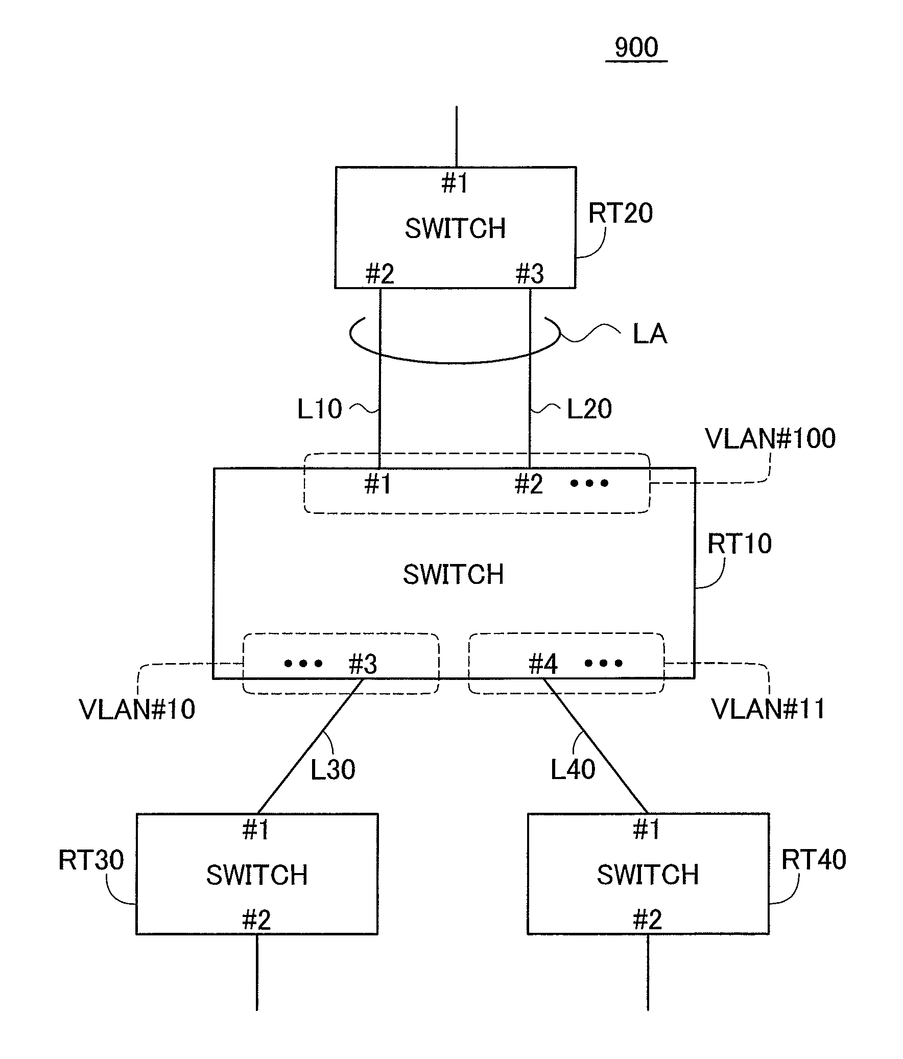
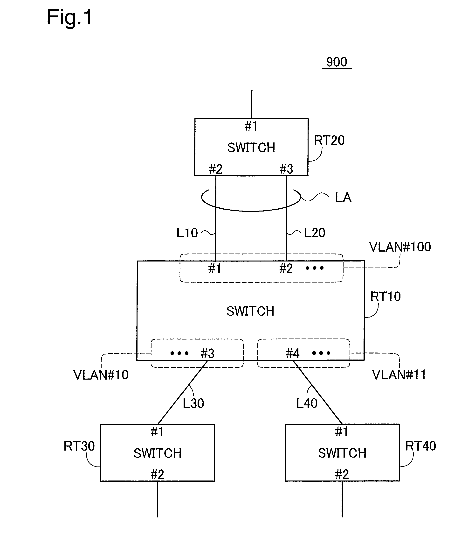
[0040]FIG. 1 is an illustration of a network system employing switch devices in an embodiment of the present invention. This network system 900 has four switch devices RT10 to RT40. In Embodiment 1, these switch devices RT10 to RT40 all function as “Layer 3 switches” (also called “routers”).

[0041]Three of the switch devices RT20, RT30, and RT40 are connected to the first switch device RT10. The first switch device RT10 and the second switch device RT20 are connected by two lines L10, L20. The first switch device RT10 and the third switch device RT30 are connected by a single line L30, and the first switch device RT10 and the fourth switch device RT40 are connected by a single line L40.

[0042]The switch devices RT10 to RT40 have physical ports for the purpose of connecting to the lines. In FIG. 1, physical port numbers identifying the physical ports are denoted by a combination of the symbol “#” with a number. For example, the line L10 connects to the first physical port (#1) of the f...

embodiment 2

[0072]The logical interface represents the logical interface at which the destination IP address is accessible. In the present embodiment, narrowing down the multiple physical ports to the particular physical port by which the packet should be sent is initially carried out based on groups each including one or more physical ports (discussed in detail later). Such a group constitutes a logical interface. In Embodiment 2, the VLANs mentioned earlier are utilized as such groups (logical interfaces). That is, initially, the VLAN (network segment) utilized to relay the packet will be selected.

[0073]Next hop refers to the next switch device. Specifically, when a packet is transmitted to the next hop, the packet can reach the final destination IP address. Each logical interface of the routing table 430 has associated with it a single next hop IP address accessible from that logical interface. For example, in the example of FIG. 8, the IP address IPaRT20 of the second switch device RT20 is ...


PUM


Abstract

Packets are relayed using a network relay device including a plurality of interface units. Each of the interface units includes one or more physical ports for connection to a line, and a bandwidth controller configured to control transmission bandwidth for packets received by the physical ports. Furthermore, a single specific physical port is selected as the output physical port from the distributed-control logical port based on output port group information unique to the output port group including the distributed-control logical port.

Description

CROSS-REFERENCE TO RELATED APPLICATIONS[0001]The present application claims the priority based on Japanese Patent Application No. 2006-228898 filed on Aug. 25, 2006, the disclosure of which is hereby incorporated by reference in its entirety.BACKGROUND[0002]1. Technical Field[0003]The present invention relates to a device and a method for relaying packets.[0004]2. Description of the Related Art[0005]Link aggregation based on the IEEE 802.3ad standard is a known redundant configuration for networks. By link aggregation, it is possible to aggregate a number of physical ports and treat them as a single virtual logical port. A method for distributing the communication load, by using a function to convert information (e.g. the header of a frame being transmitted) into an output value, and based on the output value, selecting a transmission cue corresponding to one of several links is also known (see Japanese Patent Published Application No. 2005-252758A).[0006]The use of bandwidth contro...

Claims


Application Information

Patent Timeline
Patent Type & Authority Patents(United States)
IPC IPC(8): G01R31/08H04L12/28H04L12/46H04L47/41
CPCH04L45/245H04L49/354H04L49/3045Y02B60/33Y02D30/50
Inventor YANO, HIROKISUGAI, KAZUOAKAHANE, SHINICHIHACHIYA, YOSHINORI
Owner ALAXALA NETWORKS
Why Eureka
Try Eureka