Digital television broadcast signal receiver

a digital television and receiver technology, applied in the direction of polarisation/directional diversity, selective content distribution, television systems, etc., can solve the problems of broadcast stations going into bankruptcy, significant variation in the signal intensity of received tv broadcast signals, and unidirectional antennas of yagi antennas, so as to prevent unnecessary scanning rotation and reduce time and the effect of scans

Inactive Publication Date: 2010-07-20
FUNAI ELECTRIC CO LTD
View PDF28 Cites 0 Cited by
  • Summary
  • Abstract
  • Description
  • Claims
  • Application Information

AI Technical Summary

Benefits of technology

[0011]An object of the present invention is to provide a digital TV broadcast signal receiver that can effectively use once stored data of each channel to prevent unnecessary scanning rotation of a multi-directional antenna, and can quickly control the antenna to point in a receiving direction to give a maximum signal intensity so as to determine and maintain a best receiving direction of the antenna, thereby steadily achieving a best receiving condition, and that can further reduce time and number of scans required to select a desired channel to receive.
[0015]In other words, the digital television broadcast signal receiver according to the present invention first determines, for one channel, a difference between a receiving direction of a multi-directional antenna stored at an initial setting and a further receiving direction of the antenna measured after a rotational shift of the antenna. Thereby, the amount of the rotational shift (difference in the receiving direction due to the rotational shift) can be easily obtained. Using the amount of the rotational shift for the one channel, it is possible to renew or rewrite the stored data of receiving directions for all channels, and hence the data of maximum signal intensities linked and corresponding thereto as well, easily in a short time by shifting the receiving direction number for each of the channels by the same amount of the rotational shift. Thus, when the multi-directional antenna rotationally shifts, it is not necessary to make measurements for all the channels again, or to consume unnecessary time and energy for adjusting the receiving direction of the multi-directional antenna, thereby making it possible to immediately provide a normal receiving of a TV broadcast signal, and preventing a user from getting irritated.

Problems solved by technology

At the same time, the Yagi antenna has a drawback that it can receive only a radio wave from one broadcast tower due to the high directivity, hence the Yagi antenna being a unidirectional antenna.
Due to the high directivity, furthermore, even a slight variation in the receiving direction of the Yagi antenna may cause a significant variation in the signal intensity of a received TV broadcast signal.
However, in countries like the United States of America, broadcast stations may go into bankruptcy while it is relatively easy to open new broadcast stations.
Accordingly, channels which could not previously be received may become receivable, while channels which could previously be received may become unreceivable.
Furthermore, the receiving conditions of digital TV broadcast signals may change due to newly built high rise buildings.
However, even with the multi-directional antenna, it may take a very long time to determine a best receiving direction of the antenna for receiving a TV broadcast signal of the channel selected by the user because a receiving direction control signal for switching the receiving direction may be output at very long intervals, thereby causing the user to get irritated.
However, when e.g. an indoor antenna is used, it is quite probable that a user would change a place of installing the antenna, or physically change a receiving direction of the installed antenna by mistake, making it likely to generate a trouble that TV images suddenly become unreceivable.
In such case, once the receiving direction of the antenna changes, data of the receiving directions for respective channels stored in the TV broadcast receiver become inaccurate and meaningless.
This causes a problem that requires a very laborious work and an unnecessary consumption of time and energy.

Method used


Image

  • Digital television broadcast signal receiver
  • Digital television broadcast signal receiver
  • Digital television broadcast signal receiver

Examples


Embodiment Construction

[0025]The best modes and preferred embodiments of the present invention will be described hereinafter with reference to the annexed drawings. Note that the specific embodiments described are not intended to cover the entire scope of the present invention, and hence the present invention is not limited to only the specific embodiments.

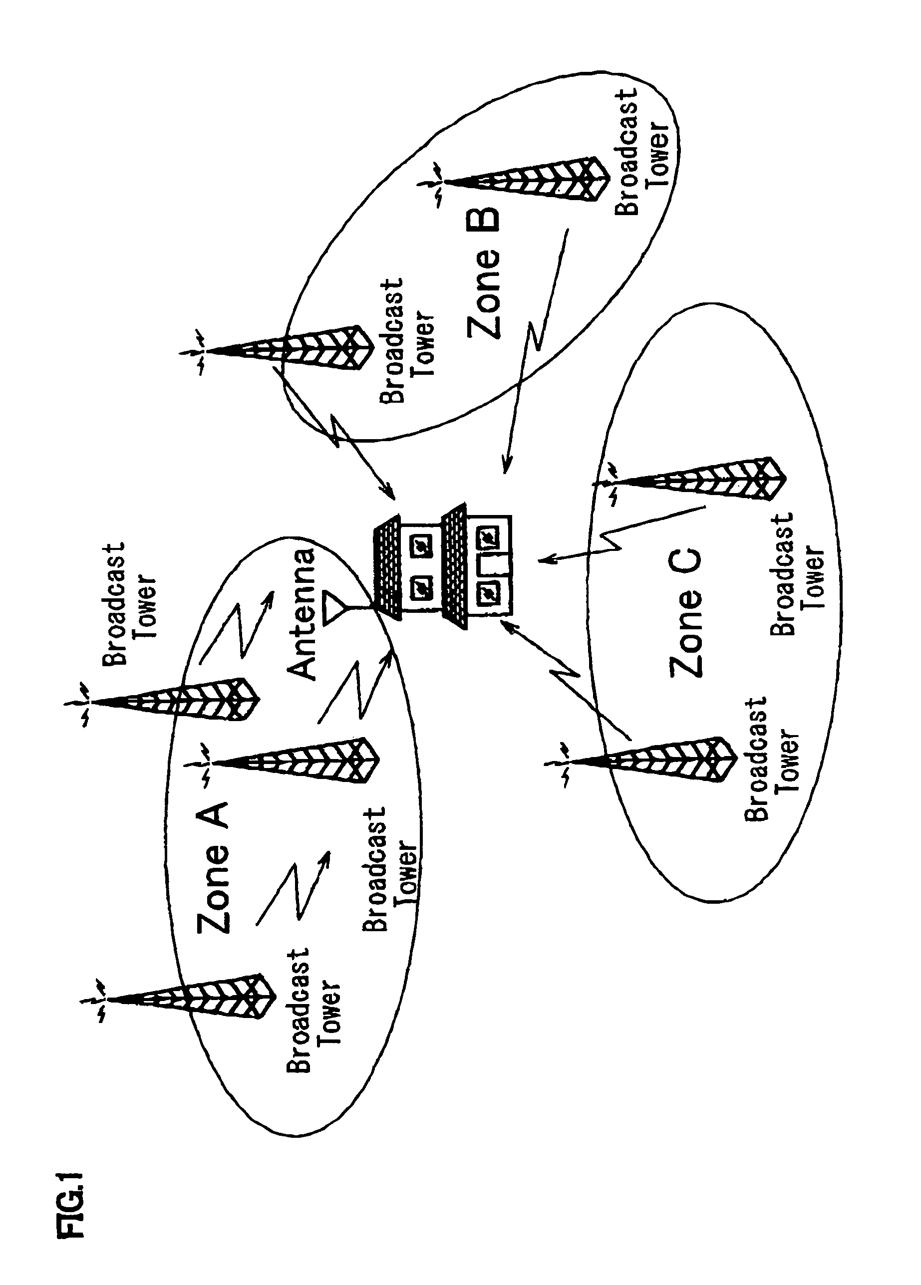
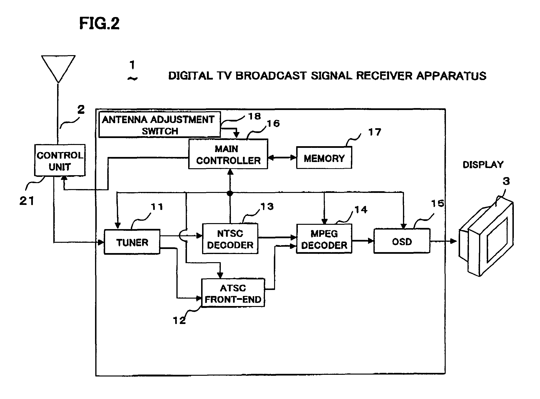
[0026]A digital TV (Television) broadcast signal receiver according to an embodiment of the present invention will be described. FIG. 1 is a schematic view showing a situation in which a digital TV broadcast signal receiver, installed in a home of a user, such as a digital TV broadcast signal receiver 1 shown in later described FIG. 2 receives digital TV broadcast signals from broadcast towers located in various zones. Generally, if a digital TV broadcast signal receiver receives digital TV broadcast signals of digital (terrestrial) TV broadcast which have a signal intensity equal to or higher than a predetermined threshold value, it is possible to obta...


PUM


Abstract

A TV receiver preliminarily measures and stores, in a memory, data of best receiving directions, each giving maximum signal intensity, of a multi-directional antenna for receivable channels. When the antenna rotationally shifts physically for some reason, one channel is selected and subjected to measurements by an omni-directional scanning again to determine a new best receiving direction. A receiving direction number difference between the stored best receiving direction and the new best receiving direction of the same channel is determined. Using the receiving direction number difference for the one channel, all data stored in the memory are renewed at one time, the data being the best receiving direction numbers and the signal intensities therefor for all the channels. The antenna direction can be quickly adjusted to the rotational shift by new measurements for one channel, without requiring time to make unnecessary measurements for all channels, achieving a best receiving condition steadily.

Description

BACKGROUND OF THE INVENTION[0001]1. Field of the Invention[0002]The present invention relates to a television broadcast signal receiver for receiving digital television broadcast signals such as ATSC (Advanced Television Systems Committee).[0003]2. Description of the Related Art[0004]In the North American Continent such as the United States of America where ATSC digital television (hereafter referred to simply as “TV broadcast”) is broadcast, big cities spread across the plains. From the viewpoint of a television user or viewer to receive TV broadcast signals, which are broadcast in big cities or their suburbs, the TV broadcast signals or even one TV broadcast signal may come from various directions. Thus, it is necessary for the user to adjust the direction of an antenna in the direction of a broadcast tower transmitting a television broadcast signal of a television program which the user wishes to watch.[0005]For this reason, multi-directional antennas such as a so-called smart an...

Claims


Application Information

Patent Timeline
Patent Type & Authority Patents(United States)
IPC IPC(8): H04N7/20H01Q3/02H04B1/16H04B1/18H04B7/08H04B7/10H04N5/44
CPCH04B7/0814H04N5/50H04N21/44209H04N21/42638H04N21/4383H04N21/4345H04N5/4401H04N21/426
Inventor TAKAGI, TOSHIHIRONAGAMURA, YOSHIHISAINUI, YASUHIRO
Owner FUNAI ELECTRIC CO LTD
Why Eureka
Try Eureka