
Magnetostrictive torque sensor and electric power steering apparatus

a torque sensor and torque sensor technology, applied in the direction of instruments, force/torque/work measurement apparatus, instruments, etc., can solve the problems of deteriorating mounting performance of a vehicle or an apparatus, corresponding strains generating corresponding strains causing errors in the detected torsional torque, so as to reduce the size of the electric power steering apparatus, and improve the overall detection accuracy

Active Publication Date: 2010-07-27
HONDA MOTOR CO LTD
View PDF13 Cites 6 Cited by
  • Summary
  • Abstract
  • Description
  • Claims
  • Application Information

AI Technical Summary

Benefits of technology

This configuration enhances torque detection accuracy, reduces size, and improves reliability by minimizing errors from bending moments and temperature gradients, facilitating easier mounting and improved steering sensation in electric power steering systems.

Problems solved by technology

Accordingly, the total length of the rotary shaft 99 becomes too long, such that a size of the magnetostrictive torque sensor 90 becomes rather large, thereby deteriorating mounting performance to a vehicle or an apparatus.
Furthermore, when the sensor 90 is used in a condition where a bending moment is applied to the rotary shaft 99, a strain due to the bending moment causes an error of the detected torsional torque.
The different bending moments and corresponding strains generate an error in the detected torsional torque.
In particular, when the axial distances between the respective detection coils are relatively long, the differences between the bending moments increase, wherein an error in the detected or measured torque increases.
In such a case, a temperature distribution in the steering shaft is not uniform, and the temperature in a lower portion of the steering shaft closer to the engine becomes higher than that of an upper portion of the steering shaft which is remote relative to the engine.

Method used


Image

  • Magnetostrictive torque sensor and electric power steering apparatus
  • Magnetostrictive torque sensor and electric power steering apparatus
  • Magnetostrictive torque sensor and electric power steering apparatus

Examples


Embodiment Construction

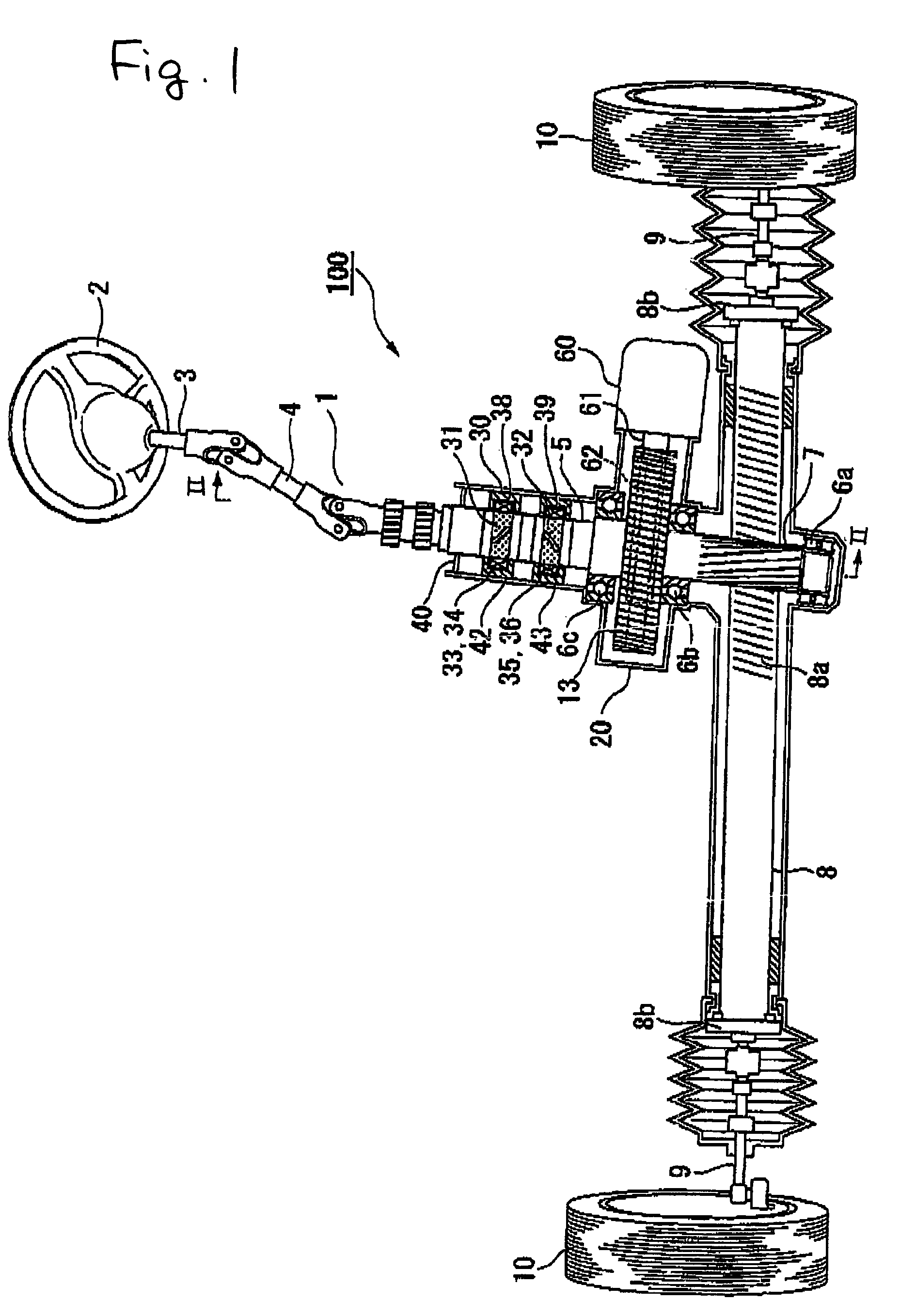
[0033]Hereinafter, a magnetostrictive torque sensor and an electric power steering apparatus according to an embodiment of the invention will be described with reference to FIGS. 1 to 3.

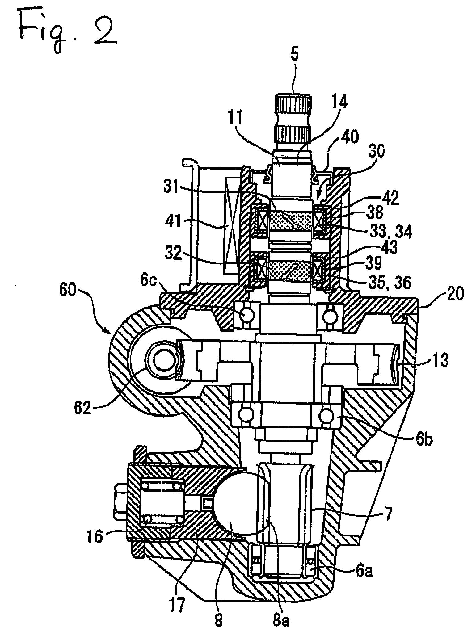
[0034]FIG. 1 is a schematic diagram showing a configuration of an electric power steering apparatus 100 of a vehicle, and FIG. 2 is a cross-sectional view taken along line II-II of FIG. 1.

[0035]The power steering apparatus 100 includes a steering shaft 1 connected to a steering wheel 2 (operation element). The steering shaft 1 includes a main steering shaft 3 integrally joined to the steering wheel 2, a pinion shaft 5 integrally provided with a pinion 7 of a rack and pinion mechanism, and a universal joint 4 which connects the main steering shaft 3 and the pinion shaft 5.

[0036]The pinion shaft 5 is accommodated in a gear housing 20. A lower part of the pinion shaft 5 is supported by a bearing 6a, and an intermediate part of the pinion shaft 5 is supported by at least one of bearings 6b and 6c. A worm...


PUM

PropertyMeasurementUnit
magnetostrictiveaaaaaaaaaa
magnetic anisotropyaaaaaaaaaa
magnetic anisotropiesaaaaaaaaaa

Abstract

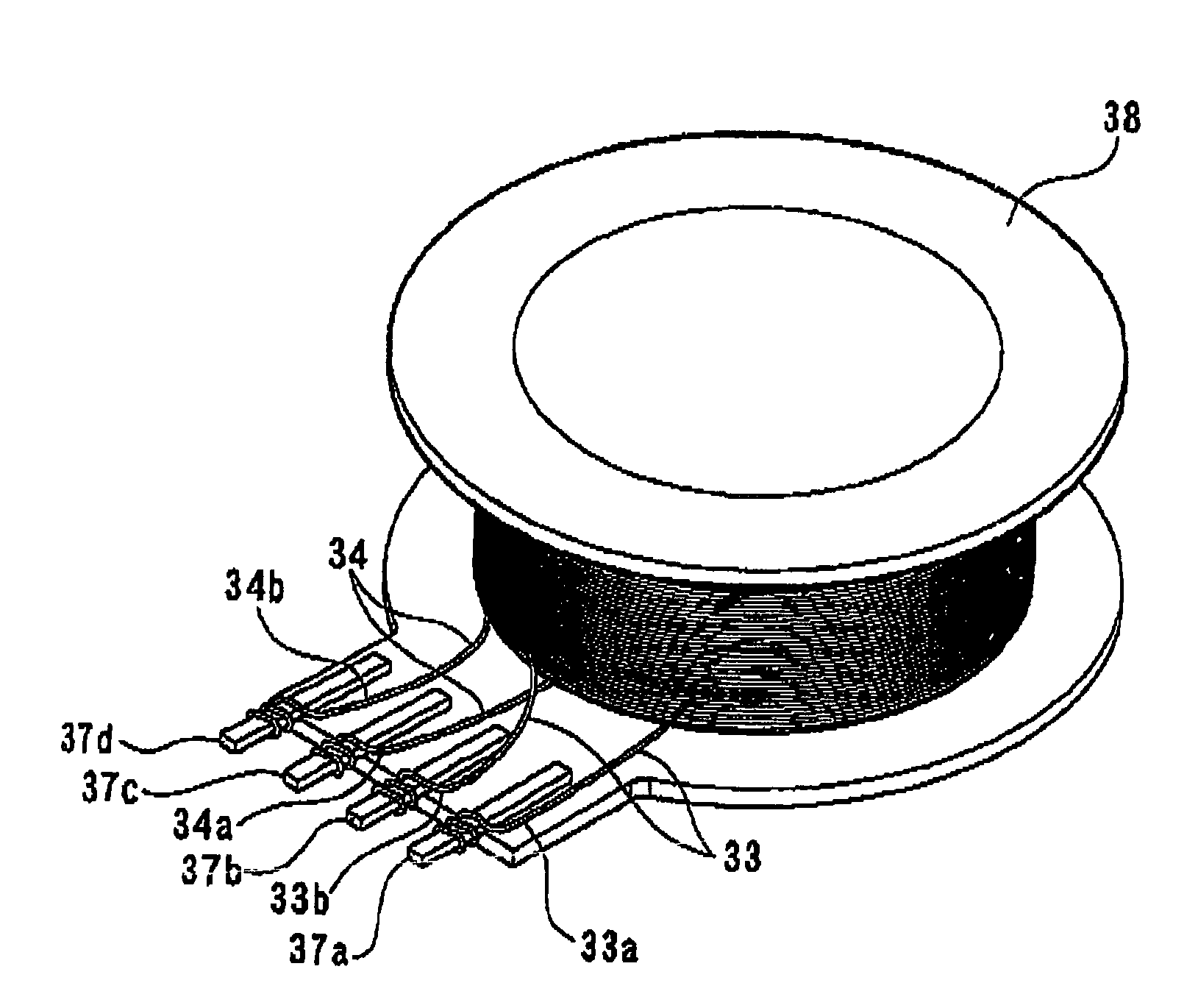
A magnetostrictive torque sensor having a first magnetostrictive film and a second magnetostrictive film, which are both provided on a shaft and have different magnetic anisotropies. A first detection coil and a second detection coil are arranged to face the first magnetostrictive film, and a third detection coil and a fourth detection coil are arranged to face the second magnetostrictive film. The first and second detection coils are wound around the same coil bobbin, while the third and fourth detection coils are wound around another common coil bobbin.

Description

[0001]The present invention claims priority from Japanese Patent Application No. 2006-133844 filed on May 12, 2006, the entire content of which is incorporated herein by reference.BACKGROUND OF THE INVENTION[0002]1. Technical Field[0003]The present invention relates to a magnetostrictive torque sensor which has improved accuracy in detecting a torque on the basis of a change in magnetic characteristics resulting from a magnetostriction and a downsized or smaller electric power steering apparatus including the same.[0004]2. Description of the Related Art[0005]As a non-contact torque sensor, a magnetostrictive torque sensor, which detects a torque on the basis of a change in magnetic characteristics resulting from a magnetostriction, is known and used as a torque sensor for detecting a steering torque of an electric power steering apparatus (see, e.g., JP-A-2006-064445).[0006]As shown in FIG. 4, a known magnetostrictive torque sensor 90, which is disclosed in JP-A-2006-064445, include...

Claims


Application Information

Patent Timeline
Patent Type & Authority Patents(United States)
IPC IPC(8): G01L3/00
CPCB62D6/10G01L3/102G01L5/221
Inventor SHIMIZU, YASUOSUEYOSHI, SHUNICHIRO
Owner HONDA MOTOR CO LTD
Learn More