Residential flood control unit

a flood control and residential technology, applied in dams, marine site engineering, construction, etc., can solve the problems of destroying family belongings, engulfing entire towns, and threatening the loss of forever family heirlooms such as photographs, antiques and other irreplaceable items, so as to effectively prevent the bladder unit from traveling along the ground surface. , the effect of preventing the fluid from entering the bladder

Inactive Publication Date: 2010-07-27
SMITH CLARENCE E
View PDF16 Cites 28 Cited by
  • Summary
  • Abstract
  • Description
  • Claims
  • Application Information

AI Technical Summary

Benefits of technology

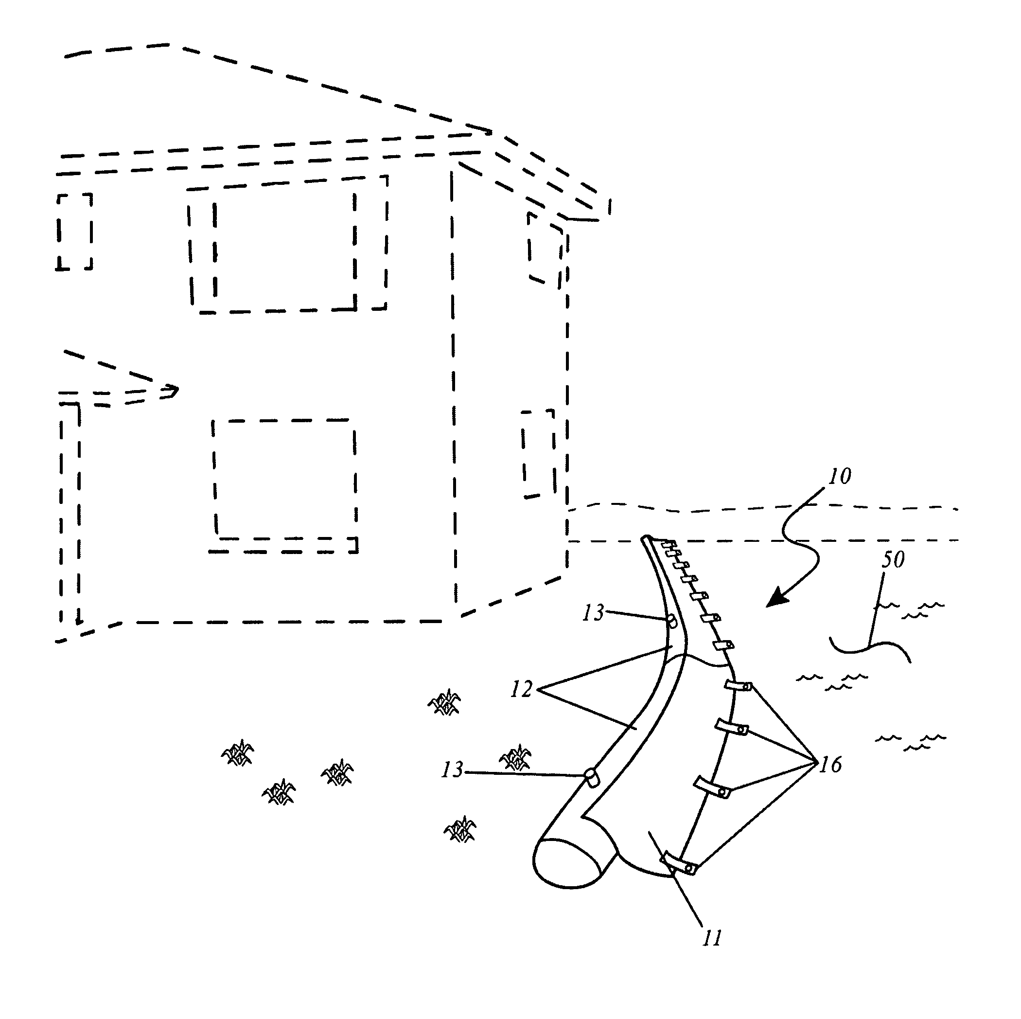
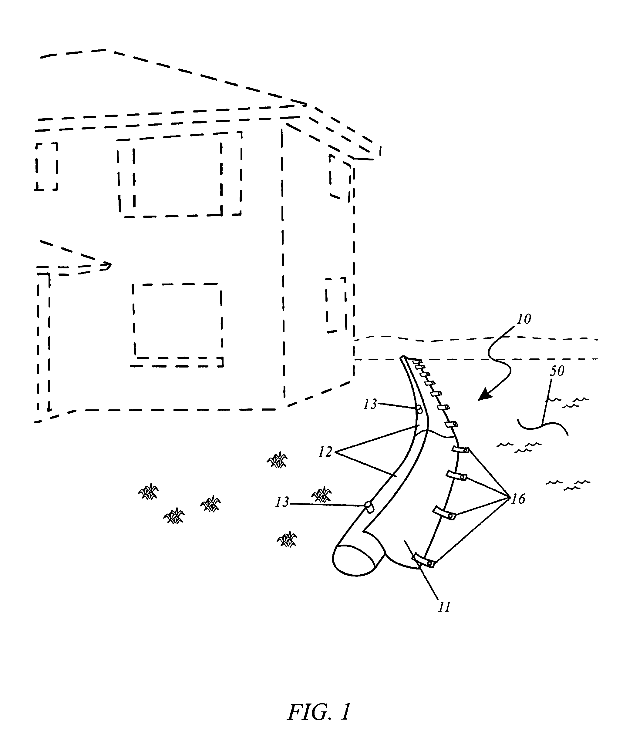
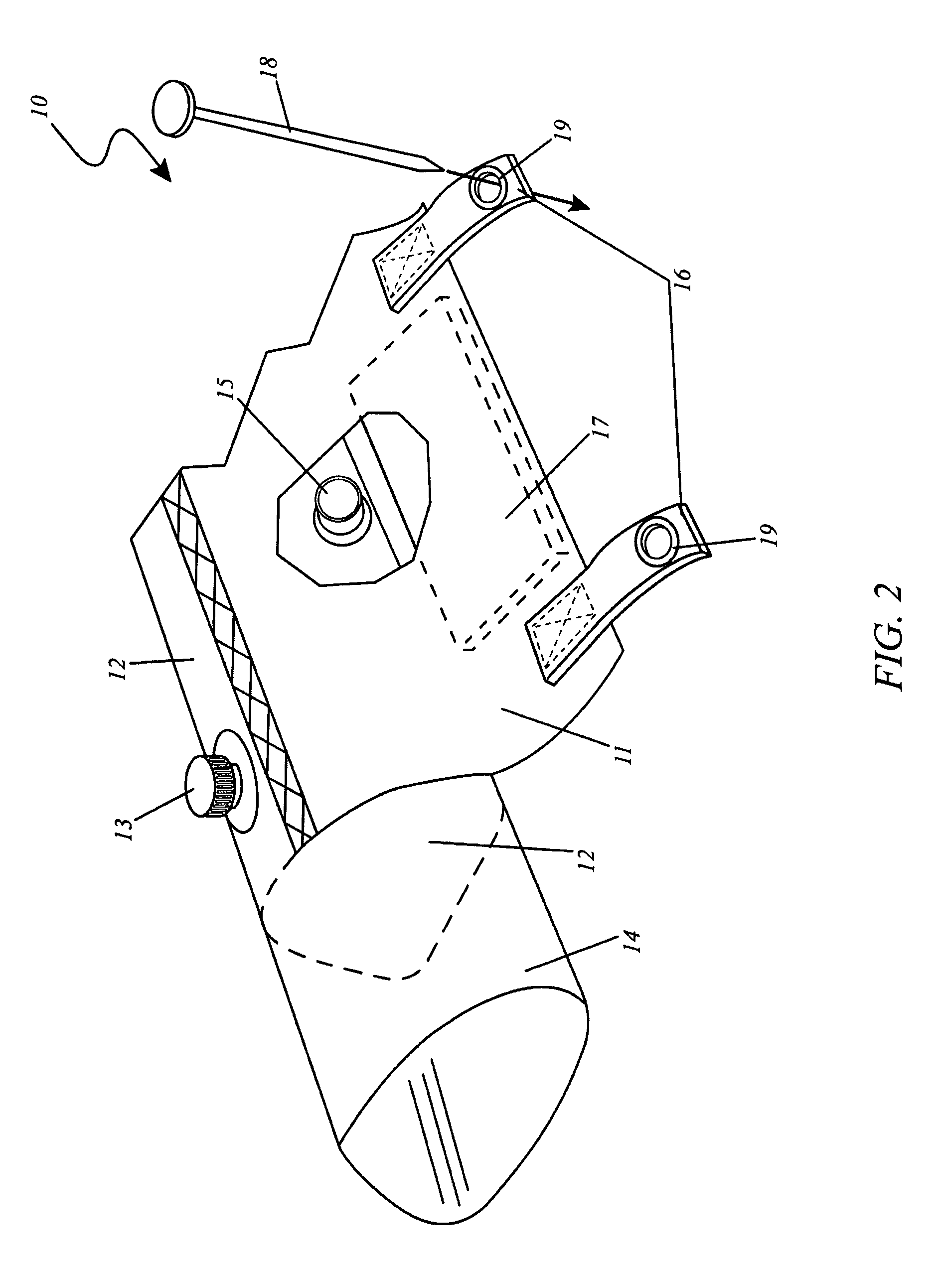
[0012]The apparatus further includes a plurality of flaps pivotally attached to each of the bladder units respectively, and each bladder is advantageously provided with a fill plug and a drain plug operably attached thereto. The flaps further include at least one pouch formed along a body thereof, and at least one weight member removably positioned within the pouch for effectively preventing the bladder unit from undesirably traveling along the ground surface. For example, when a quantity of water contacts the apparatus, the force of the water will displace the apparatus from its desired position if not for the weights. The flaps are attached to an upper central region of the bladder units and extend along an entire longitudinal length thereof respectively. The flaps further extend downwardly and outwardly along a ground level towards the flood waters. The flaps are connected longitudinally to an upper central region of the bladder unit and extend downwardly and outwardly to approximately double a diameter of the bladder.
[0013]The fill plug is located on an upper half surface of the bladder unit, and includes a tubular orifice provided with a threaded cap attached thereto. Such a fill plug allows a user to easily introduce fluid into the bladder via the use of an existing garden hose attached to a building water spigot, as an example. The drain plug is located on a lower half of the bladder unit for draining the fluid out from the bladder unit. Such a drain plug allows a user to easily drain fluid from the bladder by removing the drain plug and exerting a downward force on the bladder until the desired quantity of fluid is removed therefrom.
[0014]The apparatus further includes a mechanism for advantageously anchoring the flaps to the ground during operating conditions, which is vital such that the bladder units are effectively prohibited from being displaced along the ground surface. The anchoring mechanism includes a plurality of anchoring straps and a plurality of anchoring rods. Such anchoring straps are permanently coupled directly to the flap, without the use of intervening elements, and terminate away from a lateral edge thereof. Each of the anchoring straps is advantageously provided with an eyelet wherein the anchoring rods are driven through the eyelets and int...

Problems solved by technology

This is especially the case when dealing with floods where water can rise at alarming rates, engulfing entire towns and destroying family belongings that have been collected over many generations.
As a result, family heirlooms such as photographs, antiques and other irreplaceable items risk being lost forever, without hope for recovery.
Unfortunately, with the exception of sandbags, dikes, and massive construction projects, there is little that can be done to protect ones home or building against the ravages of a flood.
Unfortunately, such a prior art system is cumbersome to move and store, is difficult to erect, and requires use of a pum...

Method used


Image

  • Residential flood control unit
  • Residential flood control unit
  • Residential flood control unit

Examples


Embodiment Construction

[0023]The best mode for carrying out the invention is presented in terms of its preferred embodiment, herein depicted within FIGS. 1 through 2. However, the invention is not limited to the described embodiment and a person skilled in the art will appreciate that many other embodiments of the invention are possible without deviating from the basic concept of the invention, and that any such work around will also fall under scope of this invention. It is envisioned that other styles and configurations of the present invention can be easily incorporated into the teachings of the present invention, and only one particular configuration shall be shown and described for purposes of clarity and disclosure and not by way of limitation of scope.

[0024]The terms “a” and “an” herein do not denote a limitation of quantity, but rather denote the presence of at least one of the referenced items.

[0025]The present invention describes an apparatus and method for a residential flood control system (he...


PUM


Abstract

The present invention comprises an apparatus that is designed to hold back flood waters via a series of interconnected long flexible tubular units. Each unit is connected to each other via a sleeve and has a weighted flap portion for additional anchoring. Each unit has its own fill tube and drain plug and is designed to retain water or other liquid to provide an impervious water barrier when in deployment.

Description

RELATED APPLICATIONS[0001]This application claims the benefit of U.S. Provisional Application No. 60 / 778,602 filed on Mar. 3, 2006, the entire disclosures of which are incorporated herein by reference.FIELD OF THE INVENTION[0002]The present invention relates generally to a system and method to restrain minor flooding near residential structures via a series of interconnected, flexible tubular units and, more particularly, to each tubular unit connected one to the other by means of a weighted flap portion for additional anchoring.BACKGROUND OF THE INVENTION[0003]When disaster strikes, every second counts in preventing the loss of life or property. This is especially the case when dealing with floods where water can rise at alarming rates, engulfing entire towns and destroying family belongings that have been collected over many generations. As a result, family heirlooms such as photographs, antiques and other irreplaceable items risk being lost forever, without hope for recovery. Thi...

Claims


Application Information

Patent Timeline
IPC IPC(8): E02B7/02E02B7/20
CPCE02B3/108
Inventor SMITH, CLARENCE E.
Owner SMITH CLARENCE E
Why Eureka
Try Eureka