Prosthetic foot with heel and keel springs

a technology of keel springs and prosthetic feet, applied in the field of prosthetic feet, can solve problems such as affecting the amount, and achieve the effects of increasing the space for spring compression, adjusting the relative stiffness of the springs, and reducing the amount of compression

Inactive Publication Date: 2010-07-27
AMERICAN PROSTHETIC COMPONENTS
View PDF16 Cites 18 Cited by
  • Summary
  • Abstract
  • Description
  • Claims
  • Application Information

AI Technical Summary

Benefits of technology

[0018]Another advantage of the prosthetic foot of the present invention is that the foot spring is comprised of the keel spring and the heel spring. In this regard, the keel spring and heel spring are coacting springs even though they can be separated by a rigid center support. Further, the keel spring, or at least a portion thereof, is located rearward of at least a portion of the heel spring. This advantageously allows for increased space for spring compression of the keel spring and heel spring in the limited space of the prosthetic foot.
[0019]Related, a further advantage of the prosthetic foot of the present invention is that the present invention provides support to the person at mid-stance. This is accomplished by flexing of the keel and heel, and of compression of the keel spring and the heel spring. This flexing and compression relieve problems that may normally be associated with flat foot. Further, the energy in the heel strike and heel spring is useful in propelling the foot towards toe-off, and, alternatively, the energy in the keel and keel spring can be useful in assisting the person onto the heel strike if the person chooses to rock backwards.
[0020]A still further advantage of an embodiment of the present invention is that the spring portions of the keel and heel, respectively, are adapted to removably receive compression members. In this regard, the relative stiffness of the springs can be adjusted. Related, a channel is formed into each of the two side pieces in the split section of the keel spring. Each side can receive a compression member of a different stiffness.
[0021]In an alternative embodiment, the compression members can be permanently received within the heel and keel and the stiffness of the compression members can be adjusted. The stiffness can be adjusted via changing the air pressure or by adjusting electro-mechanical hardware embedded within the compression members.
[0022]A further advantage yet of the prosthetic foot of the present invention is that the present invention is free of sharp angles. Sharp angles in a prosthetic foot can lead to stress concentrations. Avoiding stress concentrations decreases the likelihood of failure of the foot.
[0023]A still further advantage yet of the present invention is that it is customizable to suit the specific needs of a given person. The heel and keel blades are removably connected to the center support, and the blades can be easily interchanged.

Problems solved by technology

Further, varying the location of the heel will affect the amount of flexing and deflection of the heel strike and compression of the heel spring at heel-strike.

Method used


Image

  • Prosthetic foot with heel and keel springs
  • Prosthetic foot with heel and keel springs
  • Prosthetic foot with heel and keel springs

Examples


Embodiment Construction

[0045]While the invention will be described in connection with several preferred embodiments, it will be understood that it is not intended to limit the invention to those embodiments. On the contrary, it is intended to cover all alternatives, modifications and equivalents as may be included within the spirit and scope of the invention as defined by the appended claims.

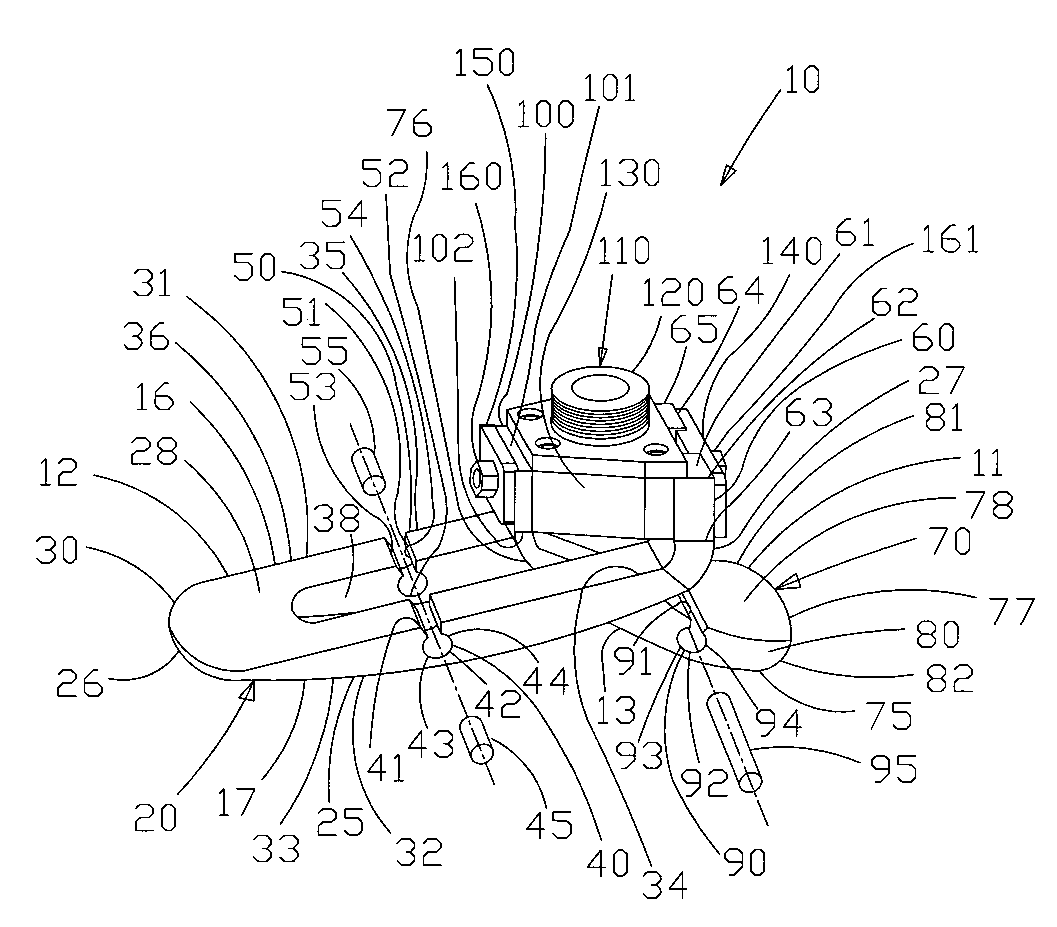
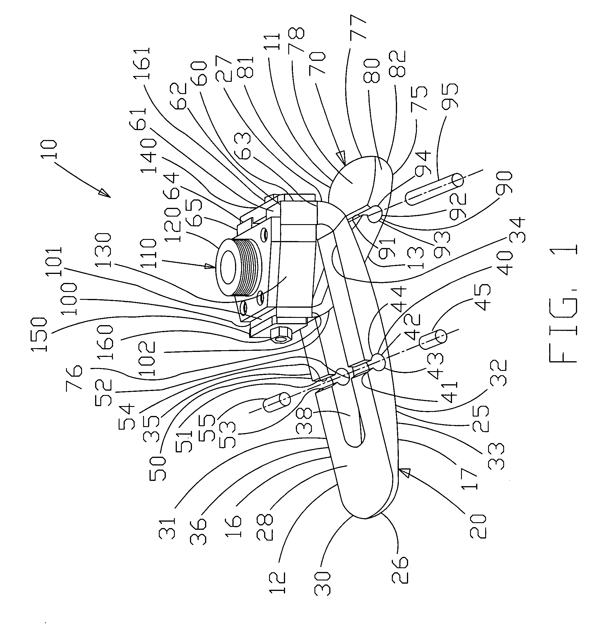
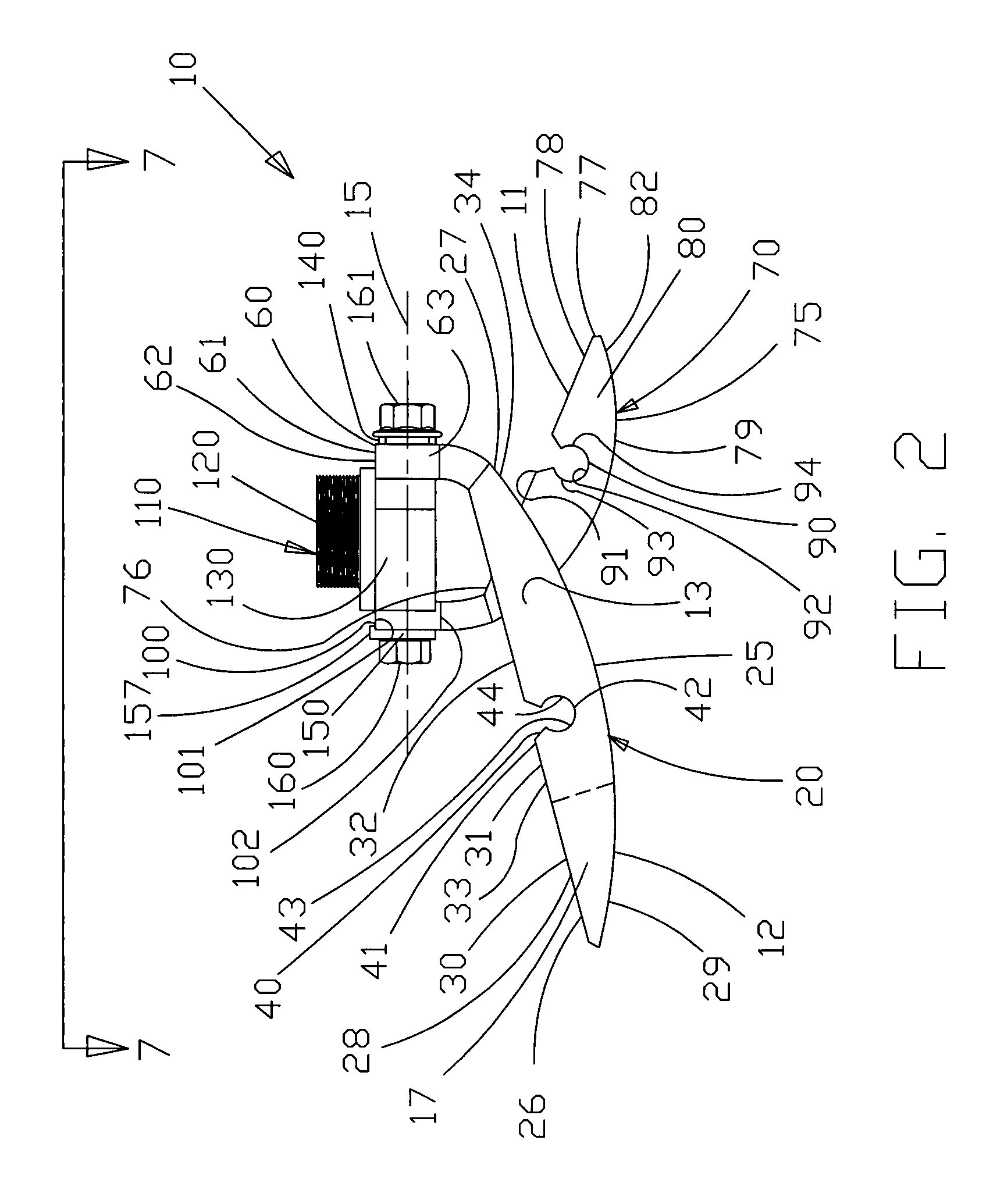
[0046]Looking first to FIGS. 1-7, it is shown that a prosthetic foot 10 is provided. The foot 10 is generally comprised of a rear portion 11 and a front portion 12. A foot spring 13 is provided between the front and rear of the foot 10. In this illustrated embodiment, the foot spring 13 generally has scissor shape. However, it will be understood that the foot spring 13 could have other shapes without departing from the broad aspects of the present invention. The prosthetic foot 10 of the present invention has a longitudinal axis 15 spanning the length of the foot. The longitudinal axis 15 is generally parallel with th...


PUM


Abstract

A keel is provided having a spring portion and a connecting portion. The spring portion can have a split section that is divided into two sections. Each section can have a top open channel formed therein. Each channel is compressible during compression of the keel. A compression member can be placed within each channel to control or limit the amount of keel spring compression. The connecting portion is rigidly connected to a rigid center support. The top of the center support can have a threaded connector, which allows for vertically adjustable connection of an adjacent prosthetic component. A heel is also provided having a spring portion and a connecting portion. The spring portion can have a top open channel formed therein. The channel is compressible during compression of the heel. A compression member can be placed within the channel to control or limit the amount of heel spring compression.

Description

BACKGROUND OF THE INVENTION[0001]1. Field of the Invention[0002]The present invention relates to a prosthetic foot, and more particularly to a prosthetic foot being adjustable in heel and keel spring capacities for complete customization and personalization, being adjustably vertically connectable at the ankle joint, and having a rigid angle joint.[0003]2. Description of the Related Art[0004]People frequently are in need of prosthetic limbs as a result of accidents, disease or birth defects. The need for quality prosthetic feet is high. There have been many attempts to make suitable prosthetic feet, each desiring to reach goals of safety, functionality and comfort, among other qualities. The existing prosthetic feet have achieved varying levels of success at attaining each of these stated goals. Further, many strategies have been utilized in designing prosthetic feet. Some designs are relatively noncomplicated, and seek to use a simple design. Other designs are complex, and seek to ...

Claims


Application Information

Patent Timeline
Patent Type & Authority Patents(United States)
IPC IPC(8): A61F2/66
CPCA61F2/66A61F2002/5009A61F2002/6614A61F2002/6657
Inventor CURTIS, MICHAEL J.
Owner AMERICAN PROSTHETIC COMPONENTS
Why Eureka
Try Eureka