Control of centrifuges

a centrifuge and control technology, applied in centrifuges, gravity filters, feed/discharge settling tanks, etc., can solve the problems of reducing the volume of slurry processed, reducing the accuracy of centrifuges, so as to maximise the performance and utilisation of centrifuges, the effect of maximising the loading of basket slurry and improving the process

Active Publication Date: 2010-07-27
THOMAS BROADBENT & SONS
View PDF10 Cites 2 Cited by
  • Summary
  • Abstract
  • Description
  • Claims
  • Application Information

AI Technical Summary

Benefits of technology

[0020]Preferably, the laser is coupled to a computing device which enables the depth of material rotating in the basket to be monitored continuously.
[0033]In preferred embodiments of the invention therefore, there is provided a centrifuge fitted with an internally or externally mounted laser measuring unit and a PLC to monitor the depth of material rotating in the basket continuously. A laser / PLC control system measures the rate of feeding to give maximum basket slurry loading. Adjustments to various stages in the centrifuge cycle following feeding, derived from the series of laser measurements can be used to maximise the centrifuge performance and utilisation over each complete cycle.
[0034]Advantages over prior art systems include the ability to measure basket material depth frequently and continuously throughout the centrifuge cycle without contacting the material surface and without signal loss, distortion and inaccuracies that result from droplets, vapour, air movement, steam and temperature changes present in the rotating basket during processing. Further advantages can accrue from the provision of useful data to central process control to optimise each centrifuge operation, provide data to improve the process both upstream and downstream of the centrifuge and minimise both product losses and the use of resources.
[0036]Continuous measurement is made of the amount of material in the rotating centrifuge basket; for example to maximise the volume processed, minimize product losses, adjust the wash liquid used to the minimum required and set the spin time for the solids volume retained in the basket, making measurements and adjustments specific to each centrifuge cycle and providing data for process measurements and optimisation.

Problems solved by technology

This existing method of feed control described above has operational limitations, including:(a) To exert sufficient force to operate a switch (which in turn closes the feed valve 4), blade 9 is depressed below the surface of the slurry, introducing an error in depth measurement.(b) This depression generates waves on the inner surface of the slurry which result in a measurement error and vibration and overflow unless allowance is made in setting position (B) to increase margin (C)—thus reducing the volume of slurry processed.(c) For applications where the process parameters vary the rate at which the slurry flows to the basket, position (B) is set to avoid overflow in the “worst case” (i.e. highest slurry temperature, lowest viscosity, lowest solids content, etc.,).
This alternative method also has operational limitations, including:(d) The velocity of sound in air varies with the air temperature, humidity and air movement, leading to an error en depth measurement with any change in these characteristics.(e) Liquid droplets, vapours, steam and air movement in the basket all vary with the basket speed and diminish the strength of the sound pulses returned to the receiver 22.
The penalty for an overflow is severe.
Firstly the unseparated solids require reprocessing and may contaminate the separated liquid, and secondly the overflow causes basket unbalance, vibration and a centrifuge shutdown for the basket load to be rebalanced before the centrifuge cycle can proceed.

Method used


Image

  • Control of centrifuges
  • Control of centrifuges
  • Control of centrifuges

Examples


Embodiment Construction

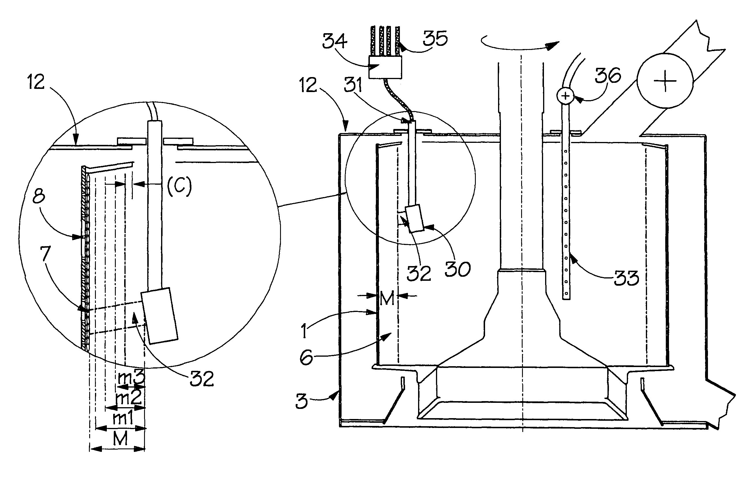
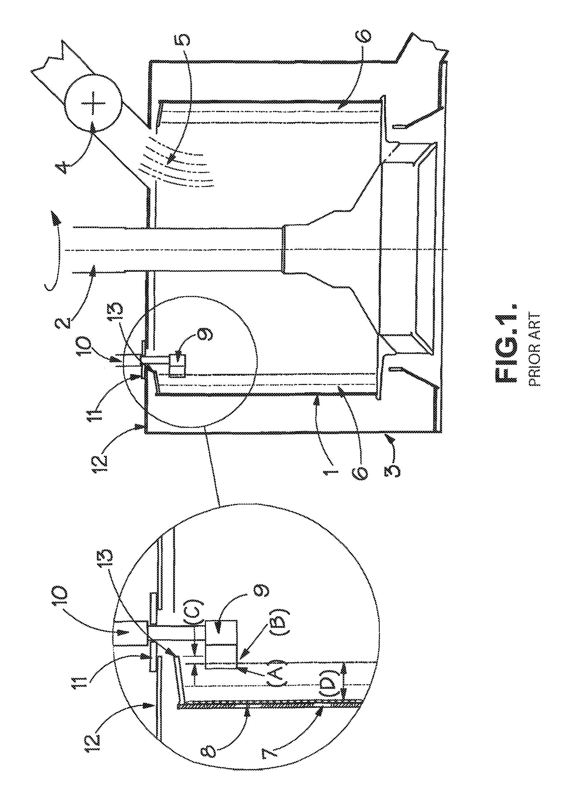
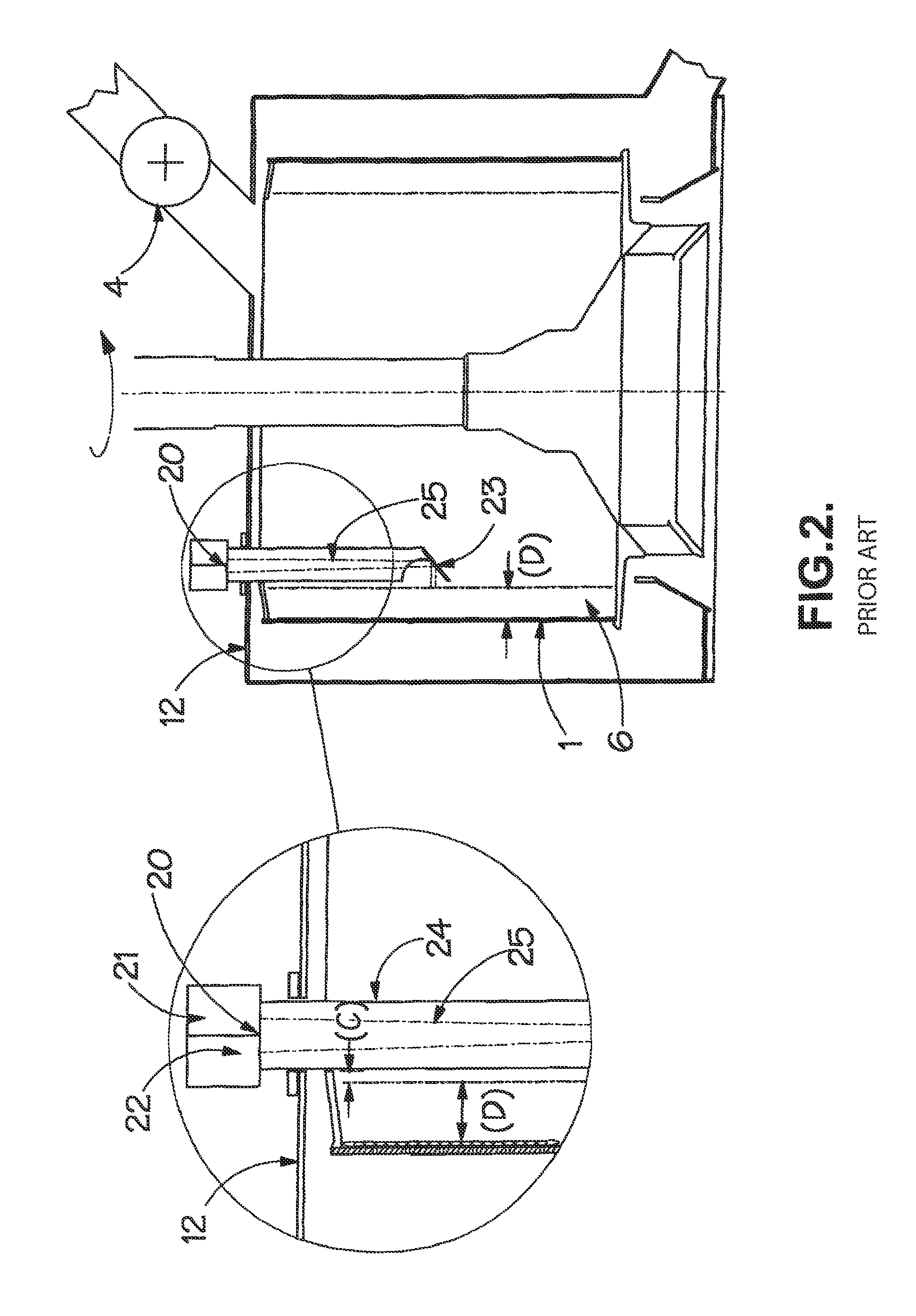
[0044]Referring now to FIG. 3, the first embodiment in accordance with the present invention has a basket 1, casing 3 and casing top 12 as in the centrifuges illustrated in FIGS. 1 and 2. The principal difference lies in the use of a laser to measure the material depth in the basket. As shown in FIG. 3, a laser unit 30 is mounted inside the basket, supported by a bracket 31 fixed to the casing top so that it is non-rotating and pointed towards the cylindrical slurry volume 6 rotating in the basket which, as shown in original FIG. 3, moves past the non-rotating laser unit 30. FIG. 4 shows an alternative arrangement with the laser unit 30 mounted on the outside of the casing top 12 and pointed indirectly to the volume 6 via a reflecting prism (or the equivalent) 37 supported inside the basket by a bracket 38. The descriptions that follow give in detail the operation of the arrangements in both FIGS. 3 and 4.

[0045]The laser unit 30 emits a continuous series of pulses (or a continuous b...


PUM

PropertyMeasurementUnit
temperaturesaaaaaaaaaa
coherent light energyaaaaaaaaaa
volumeaaaaaaaaaa

Abstract

A method of controlling a centrifuge of the type having a rotating perforated basket on whose inner peripheral wall a liquids / solids slurry is caused to collect in use, with separated liquid being collected via the basket perforations. The method comprising taking depth measurement of the material in the rotating basket continuous or at repeated intervals, over a basket cycle from commencement of slurry feed to discharge of solids, using at least one laser unit adapted to direct a beam of coherent light energy towards said inner peripheral wall of the basket of solids. The depth measurements can be made using at least one laser unit (30) adapted to direct a beam of coherent light energy towards said inner peripheral wall of the basket.

Description

FIELD OF THE INVENTION[0001]The present invention is concerned with the control of centrifuges and, in particular, of industrial centrifuges of the type comprising a rotating perforated drum or basket (hereinafter referred to as a “basket”), on whose inner peripheral wall a liquids / solids slurry is caused to collect, with the separated liquid being collected via the basket perforations.BACKGROUND OF THE INVENTION[0002]The utilisation of industrial centrifuges depends to a large extent on the control equipment fitted to ensure that the degree of separation of the solids and liquid constituents of the feed slurry meets the process requirements in the minimum time and with the minimum use of resources (power, time, wash liquid, etc.). In addition the controls should provide data for centralised overall process optimisation. By ensuring that the centrifuge is fully loaded with feed slurry and then measuring accurately and continuously the volume of material in the rotating basket as the...

Claims


Application Information

Patent Timeline
Patent Type & Authority Patents(United States)
IPC IPC(8): B04B13/00B04B11/04
CPCB04B11/043
Inventor GRIMWOOD, GEOFFREY CLIVE
Owner THOMAS BROADBENT & SONS
Why Eureka
Try Eureka