Tuning circuitry utilizing frequency translation of an impedance from a fixed-filter frequency response

a technology of frequency response and frequency translation, which is applied in the direction of frequency-changer modification, amplifier with semiconductor devices/discharge tubes, transmission, etc., can solve the problems of increasing power consumption, increasing the process of system integration, and increasing the cost, so as to facilitate system integration and improve the power dissipation of the rf tuner

Active Publication Date: 2010-07-27
SKYWORKS SOLUTIONS INC
View PDF6 Cites 15 Cited by
  • Summary
  • Abstract
  • Description
  • Claims
  • Application Information

AI Technical Summary

Benefits of technology

[0009]Yet another object of the present invention is to provide an RF tuner with improved power dissipation and system integration.
[0015]Various elements of the RF tuner of the present invention can be implemented by using Bi-CMOS technology. This eliminates the need for a variable-frequency tracking filter that requires discrete components such as wire-wound inductors, which are difficult to integrate. Further, the RF tuner requires only one local oscillator signal generator to down-convert the in-band signal frequency to Intermediate Frequency. This improves the power dissipation of the RF tuner. Further, the RF tuner does not require a SAW filter. This facilitates system integration. Moreover, the RF tuner can be used in both the analog and the digital domain, since the components can be implemented with standard analog and standard digital technology.

Problems solved by technology

However, the use of external band-pass filters downgrades the process of system integration and increases the cost.
Further, the first up-conversion process for the entire block of the input RF signal frequencies increases power consumption, which, in turn, causes high power dissipation and thus heat.
However, these elements are difficult to integrate on a single chip.
Further, there is a need to do away with discrete components such as inductors, capacitors, diodes, and the like, which face significant difficulty during the process of integration.

Method used


Image

  • Tuning circuitry utilizing frequency translation of an impedance from a fixed-filter frequency response
  • Tuning circuitry utilizing frequency translation of an impedance from a fixed-filter frequency response
  • Tuning circuitry utilizing frequency translation of an impedance from a fixed-filter frequency response

Examples


Embodiment Construction

[0026]Various embodiments of the present invention provide an RF tuner with a front-end tracking amplifier for tuning input RF signals. The RF tuner includes a frequency-dependent impedance generator. The frequency-dependent impedance generator generates a low frequency-dependent impedance at the input, for in-band signal frequency. The in-band signal frequency is the input RF signal frequency, centered at a local oscillator signal frequency. The frequency-dependent impedance generator is used with an amplifier circuit to generate a tracking amplifier with a peak gain for the in-band signal frequency. Thereby, the tracking amplifier tracks the local oscillator signal frequency.

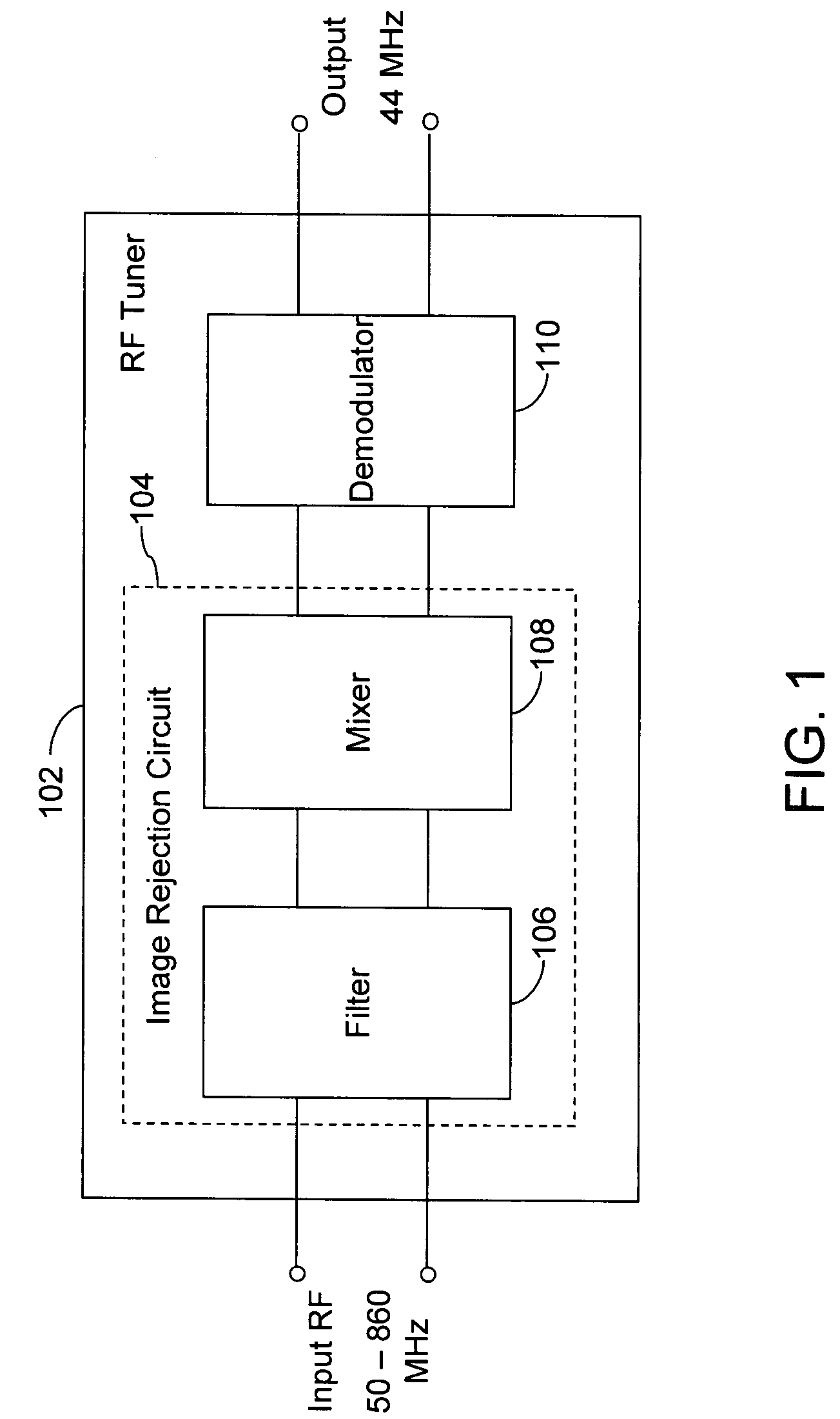
[0027]FIG. 1 is a block diagram of an RF tuner 102, in which various embodiments of the present invention may be implemented. RF tuner 102 includes an image rejection circuit 104 and a demodulator 110. Image rejection circuit 104 includes a filter 106 and a mixer 108.

[0028]RF tuner 102 receives differential in...


PUM


Abstract

A circuit and method for tracking a local oscillator signal frequency in an RF tuner, for tuning input RF signals. The RF tuner includes a frequency-dependent impedance generator that generates a frequency-dependent impedance at the input by rejecting unwanted input RF signals and shunt feeding back the desired signal to the input. The desired signal frequency is centered at the local oscillator signal frequency. The frequency-dependent impedance generator is used with an amplifier circuit to generate a tracking amplifier, the frequency-dependent amplifier gain of which tracks the local oscillator signal frequency.

Description

BACKGROUND OF THE INVENTION[0001]The present invention generally relates to RF tuners. More specifically, the present invention relates to a tracking amplifier and a band-pass impedance generator for tuning input RF signals.[0002]Broadband cable and terrestrial systems offer consumers a wide range of channels, which are spread over a broad range of RF frequencies. RF frequencies are usually in the 50-860 MHz range, with each channel having a bandwidth of 6, 7 or 8 MHz. Various products, such as television sets, set-top boxes, computer systems, and the like, deploy RF tuners (also referred to as broadband tuners) to tune to a desired channel by filtering undesired channels without altering the information carried by the desired channel.[0003]Various filtering techniques are used by RF tuners for channel selection, e.g., variable-frequency filters and fixed-frequency filters. Variable-frequency filters are usually used in Single Conversion Tuners (SCT) and fixed-frequency filters in D...

Claims


Application Information

Patent Timeline
Patent Type & Authority Patents(United States)
IPC IPC(8): H04B1/16
CPCH03D7/18H04B1/18
Inventor BAYRUNS, JOHN THOMAS
Owner SKYWORKS SOLUTIONS INC
Why Eureka
Try Eureka