
Apparatus and methods for delivering transvenous leads

a technology of transvenous leads and apparatus, applied in the direction of transvenous endocardial electrodes, internal electrodes, therapy, etc., can solve the problems of difficult initial access of the coronary sinus, difficult to reach, and not easily slipped out of pla

Active Publication Date: 2010-07-27
MEDTRONIC INC
View PDF13 Cites 69 Cited by
  • Summary
  • Abstract
  • Description
  • Claims
  • Application Information

AI Technical Summary

Benefits of technology

The present invention is about apparatus and methods for delivering leads and other instruments during a medical procedure. Specifically, it describes how to deliver leads into a patient's coronary vein system using a rail and tubular member. The technical effects of this invention include improved stability and access during a procedure, as well as the ability to deliver instruments to specific locations within the body.

Problems solved by technology

Such an approach can be difficult for a number of reasons.
Furthermore, the design objectives of a lead system optimized for delivery often conflict with the design objectives of a system optimized to remain in stable position for long term pacing.
For example, during delivery, a device is optimally lubricious and slides easily through the vasculature; however, once in place, the optimal device does not slide easily out of place, but remains in a stable position.
Another problem associated with transvenous lead delivery is maintaining stable access into the coronary sinus and the coronary veins.
Initial access of the coronary sinus may be difficult secondary to the presence of venous valve or tortuous or distorted anatomy.
Once the coronary sinus has been accessed with a sheath or guidewire or other device, maintaining access is important and may be difficult during multiple exchanges of devices, for example a venography balloon catheter or pacing lead, or when attempting to move a pacing lead from one position to anther position.

Method used


Image

  • Apparatus and methods for delivering transvenous leads
  • Apparatus and methods for delivering transvenous leads
  • Apparatus and methods for delivering transvenous leads

Examples


Embodiment Construction

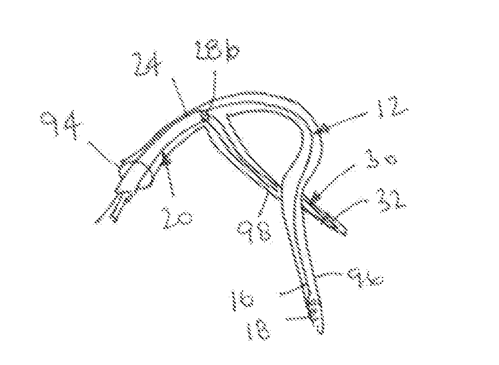
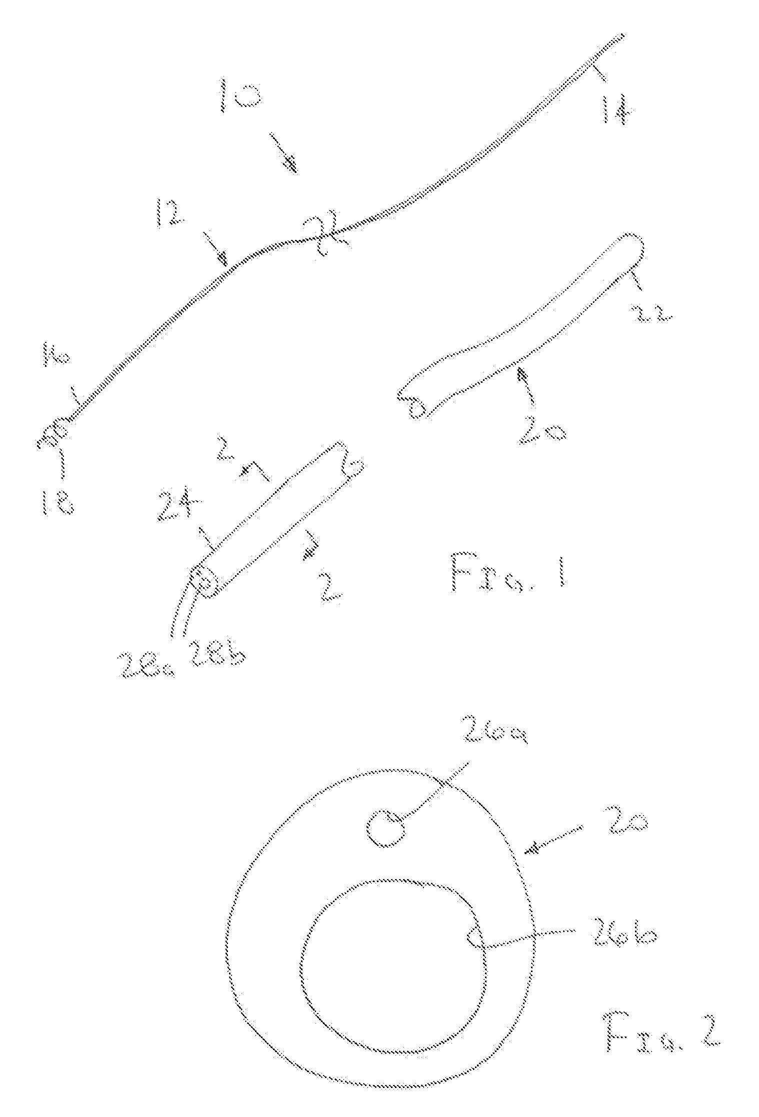
[0023]Turning to the drawings, FIG. 1 shows an exemplary embodiment of a system 10, including a guidewire or other elongate rail 12 and a catheter or other tubular member 20. The system 10 may be used for delivering a lead, e.g., a pacing or other transvenous lead (not shown), or other instrument to a location within a body lumen, as described further below.

[0024]The guidewire 12 generally includes a proximal end 14, a distal end 16, and an anchor or other fixation device 18 on the distal end 16. The guidewire 12 may be formed using known materials and methods, e.g., metal, such as stainless steel or Nitinol, plastics, or composite materials. For example, the guidewire 12 may be formed from a single strand of solid or hollow wire, multiple strands, and the like. The guidewire 12 has sufficient length to extend from a location outside a patient's body, e.g., from a percutaneous entry site into the subclavian or femoral vein, to a target location where the distal end 16 is to be secur...


PUM


Abstract

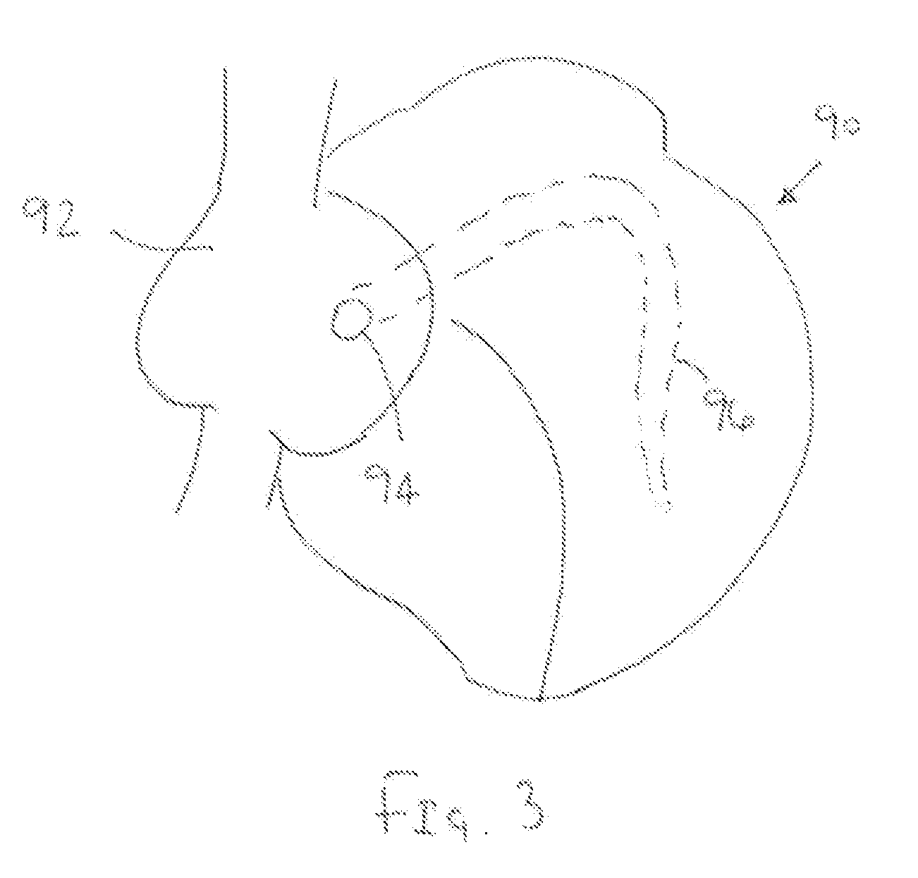
Apparatus and methods are provided for delivering a lead over a rail into a target body lumen, cavity, or other vessel, e.g., a coronary vein or a right ventricle within a patient's heart. For example, a distal end of an elongate guidewire or other rail may be introduced into the coronary venous system via the coronary sinus, advanced through the coronary venous system to a location beyond a target vessel, and secured at the location beyond the target vessel. A catheter or other elongate tubular member is advanced over the rail and manipulated to position an outlet of the tubular member adjacent to or otherwise aligned relative to the target vessel. A distal end of a lead is delivered through the tubular member and out the outlet into the target vessel. The catheter and rail are then removed, leaving the lead within the target vessel.

Description

[0001]This application claims benefit of Provisional Application Ser. No. 60 / 708,750 filed Aug. 16, 2005, the entire disclosure of which is expressly incorporated by reference herein.FIELD OF THE INVENTION[0002]The present invention relates generally to apparatus and methods for delivering leads, and, more particularly, to apparatus and methods for delivering leads or other instruments using a delivery device movable over a guidewire or other rail.BACKGROUND[0003]It is known to place pacing leads in the area of the left ventricle via the coronary veins, e.g., for bi-ventricular pacing or resynchronization therapy. During such procedures, an electrical conductor (i.e., pacing lead) must be coupled to the left ventricle. In order to accomplish this in a minimally invasive fashion, the most common approach is by way of the coronary sinus and coronary venous system.[0004]Such an approach can be difficult for a number of reasons. These include the inherent variability of venous anatomy, ...

Claims


Application Information

Patent Timeline
Patent Type & Authority Patents(United States)
IPC IPC(8): A61N1/00
CPCA61N1/057A61N1/0573A61N2001/0585
Inventor EVERSULL, CHRISTIAN S.LEEFLANG, STEPHEN A.MOURLAS, NICHOLAS J.
Owner MEDTRONIC INC
Learn More