Cooling exchanger duct

a technology of heat exchanger and cooling exchanger, which is applied in the direction of machines/engines, marine propulsion, vessel construction, etc., can solve the problems of turbofan engine thrust loss, caused by heat loss of lubricant,

Inactive Publication Date: 2010-08-03
RAYTHEON TECH CORP
View PDF12 Cites 54 Cited by
  • Summary
  • Abstract
  • Description
  • Claims
  • Application Information

AI Technical Summary

Problems solved by technology

During such lubrications, heating of the lubricant is caused to occur due to mechanical energy losses in the lubricated apparatus.
Larger heat exchangers require larger cross sectional area ducts, and such an air and lubricating oil heat exchanger duct based system continually leads to thrust losses in the turbofan engine.

Method used


Image

  • Cooling exchanger duct
  • Cooling exchanger duct
  • Cooling exchanger duct

Examples


Embodiment Construction

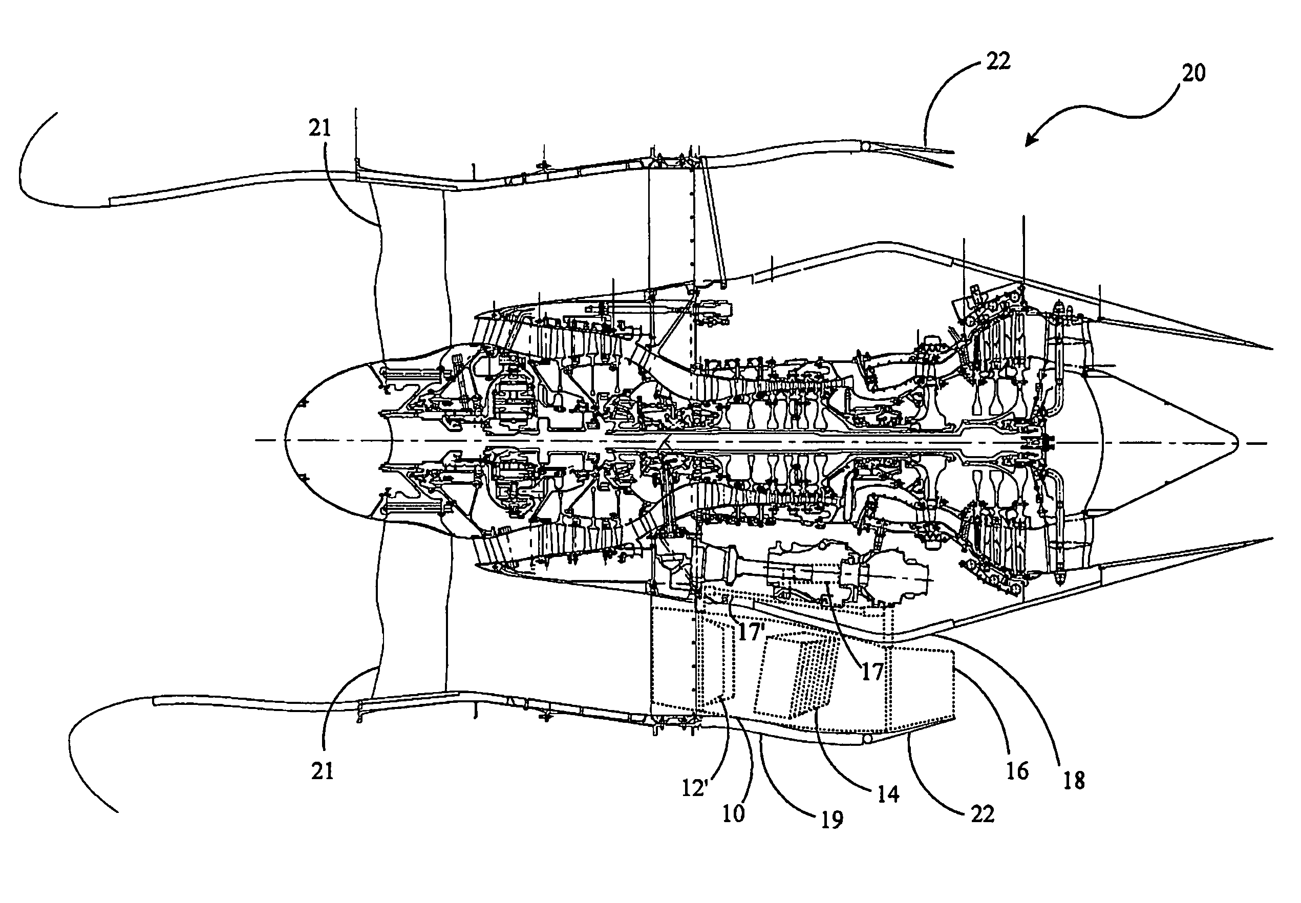
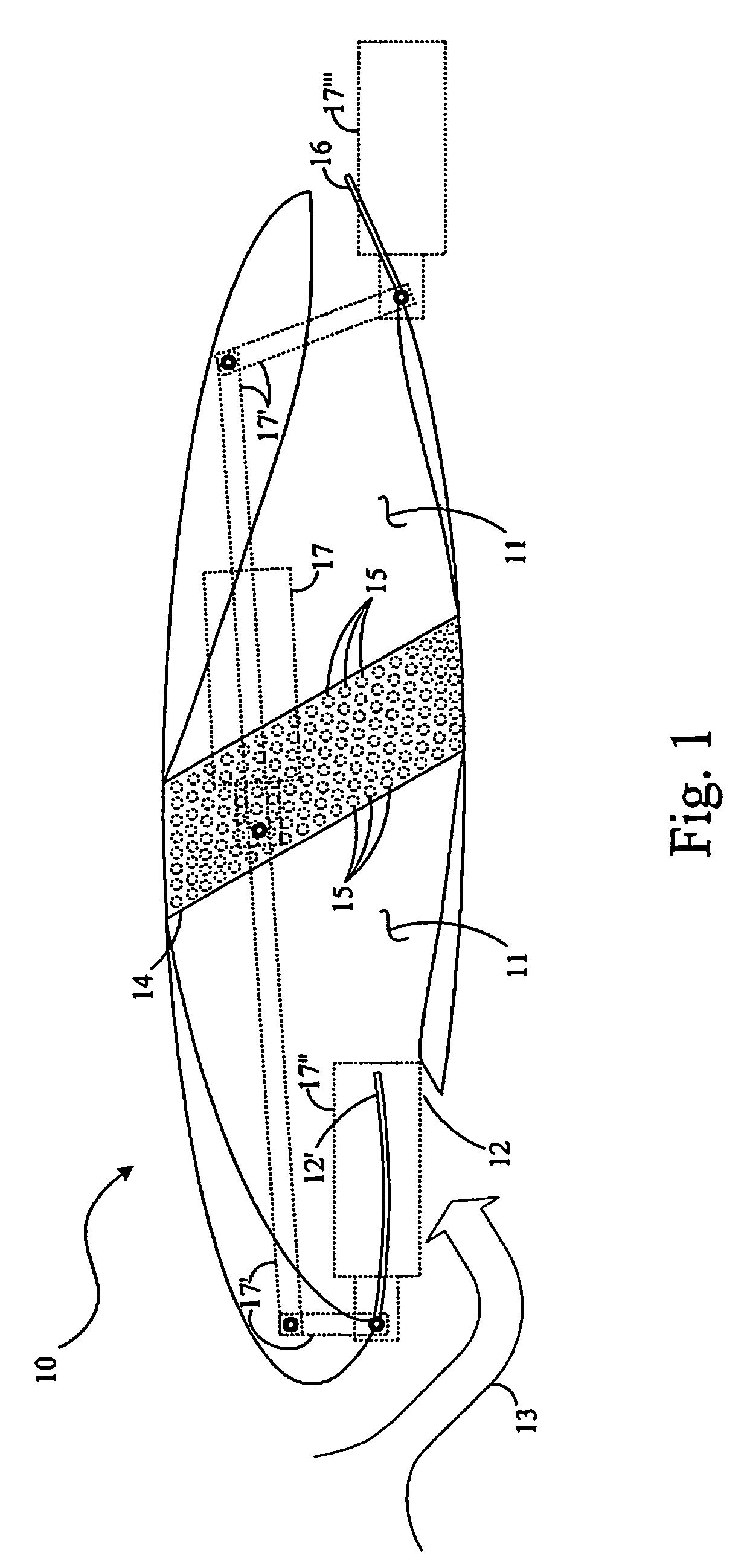
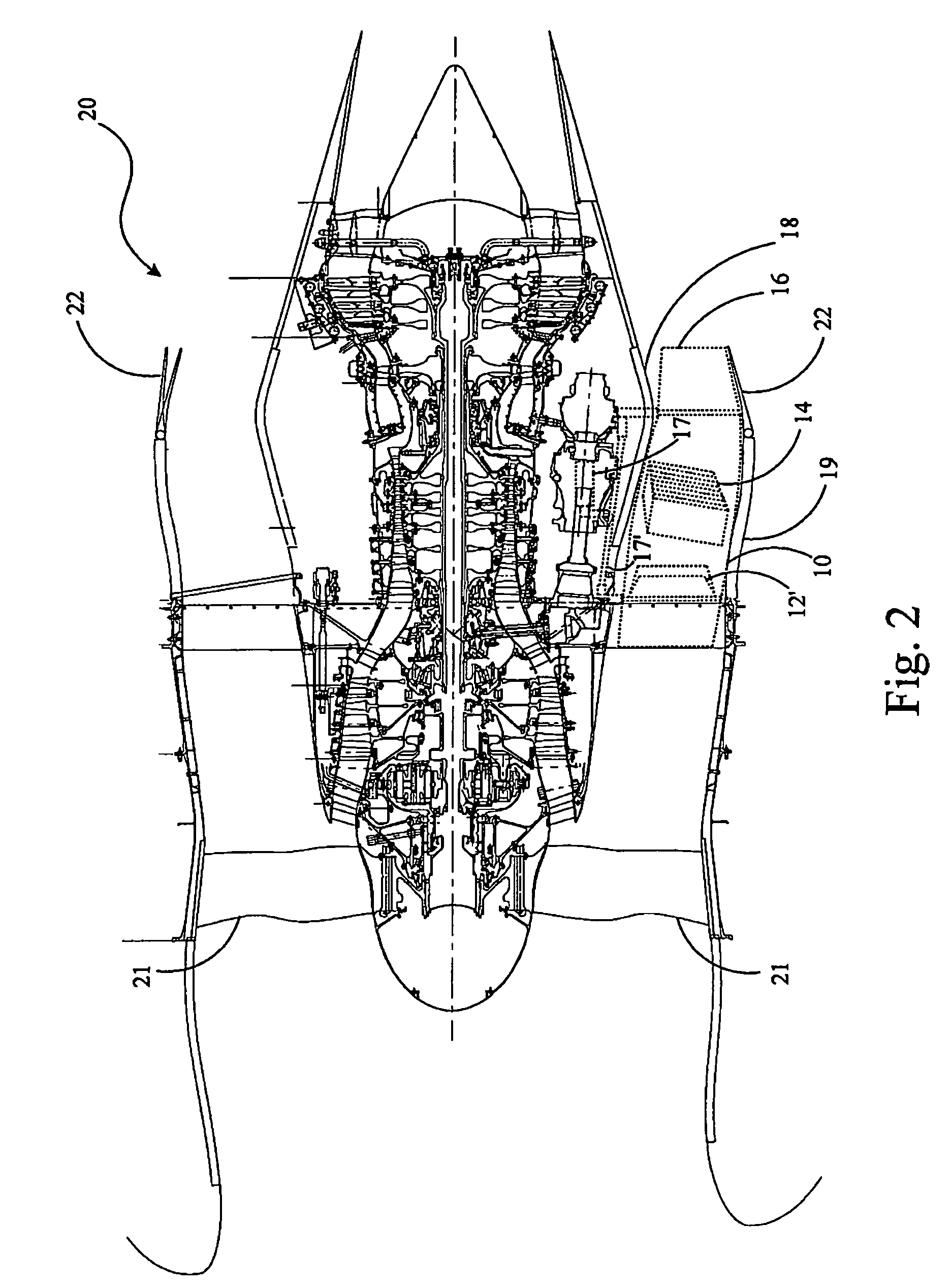
[0011]A smaller cross sectional area heat exchanger leads to enabling its use in a duct of a smaller cross sectional area to thereby improve the compactness of the resulting cooling subsystem. Achieving the same cooling of a working fluid, such as a lubricant, passing through such a smaller cross sectional area heat exchanger, generally requires that a larger volume of air pass through that heat exchanger per unit time about the passageways thereof to which the working fluid is delivered and through which the previously heated working fluid is flowing to be cooled and thereafter to subsequently be introduced to the remainder of the system making use of that fluid. Such an increase in volume rate of air passing through the heat exchanger in a smaller cross sectional area duct generally requires that the pressure gradient from the duct entrance to the duct exit be sufficiently greater to result in such a flow. Although the present invention is useable with any working fluid provided i...


PUM


Abstract

A heat exchange system for use in operating equipment in which a working fluid is utilized in providing selected operations thereof, including for use in lubricating systems for aircraft turbofan engine equipment, the heat exchange system for providing air and working fluid heat exchanges to cool the working fluid at selectively variable rates in the operating equipment developed airstreams. A heat exchanger core is provided in a controlled air flow duct system opening at its entrance to those airstreams and having its outlet end opening downstream in those airstreams.

Description

BACKGROUND OF THE INVENTION[0001]The present invention relates to lubrication systems for turbine engines and for associated equipment, and more particularly, to air and lubricant heat exchangers for use in maintaining desired temperatures of the lubricants in such engines and equipment.[0002]Lubrication systems for turbine engines, such as a turbofan engine, and for associated equipment, such as an integrated drive generator, provide pressurized lubricant, an oil, to lubricate, cool and clean the engine main bearings, gear box gears, and the like, and again for the lubrication of bearings and other parts in equipment associated with such turbine engines. During such lubrications, heating of the lubricant is caused to occur due to mechanical energy losses in the lubricated apparatus. Thermal management of such lubricants is very important for continued successful operation of such lubrication systems in the apparatus lubricated thereby.[0003]The amount of heat necessary to be ejecte...

Claims


Application Information

Patent Timeline
Patent Type & Authority Patents(United States)
IPC IPC(8): F02K99/00
CPCF02C7/14F02K3/115Y02T50/675Y02T50/60
Inventor SCHWARZ, FREDERICK M.
Owner RAYTHEON TECH CORP
Why Eureka
Try Eureka