
Refrigeration unit and diagnostic method therefor

a refrigeration unit and refrigeration technology, applied in the field of refrigeration units, can solve the problems of unnecessary replacement of normal operating lru, item spoilage, refrigeration unit may operate inefficiently, and not properly cool the items being stored insid

Active Publication Date: 2010-08-03
BE AEROSPACE INCORPORATED
View PDF13 Cites 24 Cited by
  • Summary
  • Abstract
  • Description
  • Claims
  • Application Information

AI Technical Summary

Benefits of technology

The patent describes a refrigeration unit for aircraft galleys that includes a housing with a vapor cycle system for cooling food and beverages. The unit has multiple sensors that communicate with the vapor cycle system and output data about it. A controller analyzes the data and determines if there is an event that requires a control signal to the vapor cycle system. The controller can also log the data to a data structure at different rates depending on the severity of the event. The technical effect of this patent is to provide a more efficient and effective refrigeration system for aircraft galleys that can detect and respond to events in real-time, improving operational efficiency and safety.

Problems solved by technology

Often, a normally-operating LRU is replaced unnecessarily because the LRU simply has an appearance or isolated instance of irregular operation, for example due to user error in operating the LRU.
In some instances, however, aircraft staff (e.g., inexperienced flight attendants) may mis-set the temperature set-point relative to the type of items being stored in the refrigeration unit, thereby causing item spoilage.
In yet other instances, aircraft staff may close the door to the refrigeration unit but fail to notice that the door was not properly closed and, therefore, the refrigeration unit may operate inefficiently and not properly cool the items being stored inside.

Method used


Image

  • Refrigeration unit and diagnostic method therefor
  • Refrigeration unit and diagnostic method therefor
  • Refrigeration unit and diagnostic method therefor

Examples


Embodiment Construction

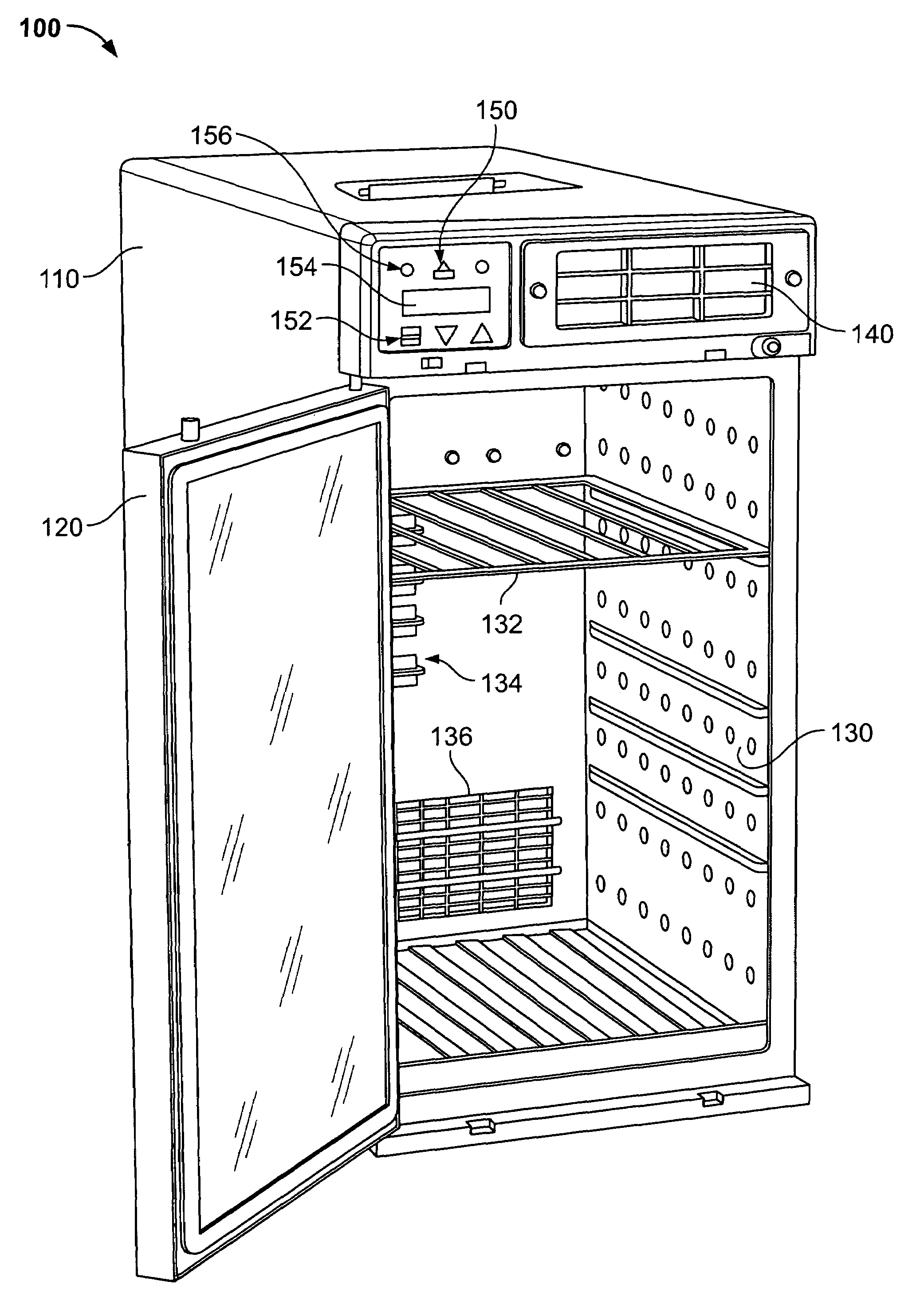
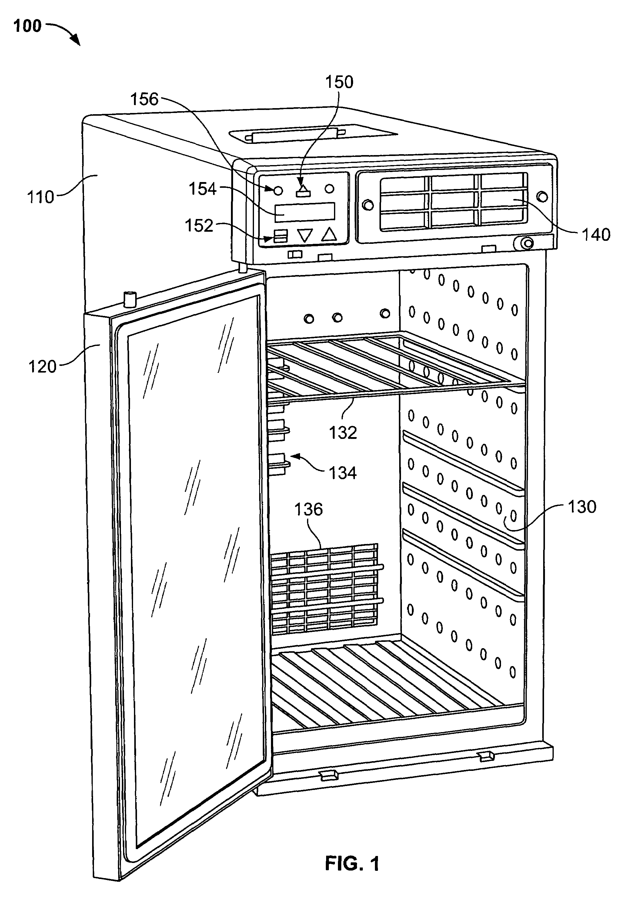
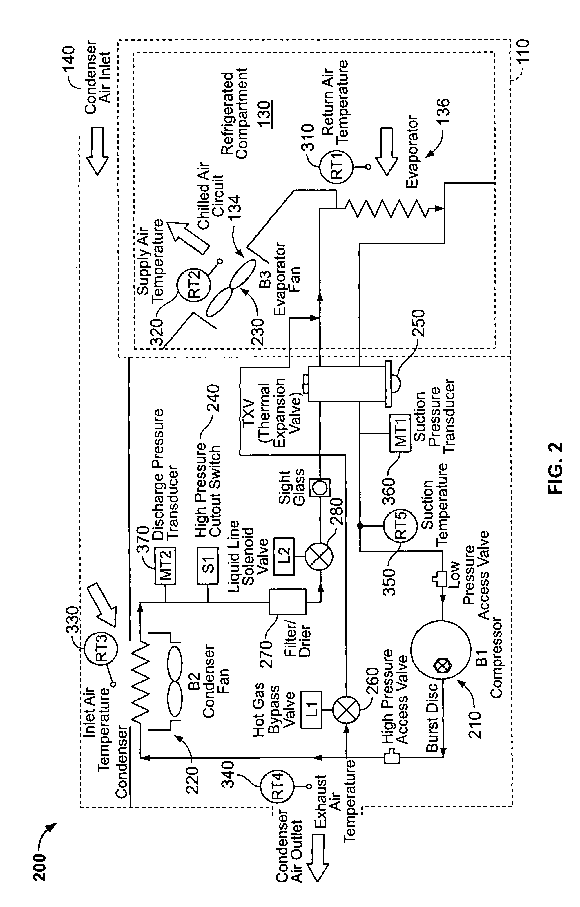
[0010]Referring now to the Figures, a refrigeration unit and a diagnostic method therefore are provided. As shown in FIG. 1, an example refrigeration unit 100 includes a housing 110, a door 120 that is coupled with the housing 110 for movement between a closed orientation and an open orientation, an insulated cavity 130 within the housing 110 for storing items (e.g., food and beverages) to be refrigerated, an air intake 140 and a user interface 150. The refrigeration unit 100 is a self-contained, stand-alone refrigeration unit that chills air for the purpose of maintaining food and beverage items at proper storage temperatures within the insulated cavity 130. As shown, the housing 110 has a generally compact, rectangular polyhedron shape to facilitate installation of the refrigeration unit 100 in a galley of an aircraft, but the housing 110 may be configured in other shapes for installation in other vehicles and locations, for example, busses, trains, vans, residences and offices. T...


PUM

PropertyMeasurementUnit
volumeaaaaaaaaaa
temperatureaaaaaaaaaa
pressureaaaaaaaaaa

Abstract

A refrigeration unit and diagnostic method therefore are provided. The refrigeration unit includes: a housing with an insulated cavity for storing food and beverages; a vapor cycle system operative to cool the food and beverages in the insulated cavity; a plurality of sensors in communication with the vapor cycle system and outputting data relative to the vapor cycle system; and a controller that, according to the data from the plurality of sensors, determines an occurrence of an event. Wherein the controller logs the data from the plurality of sensors to a data structure according to a first data-logging mode, and logs the data to the data structure according to a second data-logging mode upon occurrence of the event. In one embodiment the refrigeration unit may be a refrigeration line replaceable unit (LRU) configured for an aircraft galley.

Description

FIELD OF THE INVENTION[0001]This invention pertains generally to refrigeration units and more particularly to a chiller / refrigerator / freezer unit for an aircraft galley and a diagnostic method therefore.BACKGROUND OF THE INVENTION[0002]For operators of passenger vehicles, it is of utmost importance to minimize maintenance costs and downtime. To this end, passenger vehicle components and subsystems are modularized to facilitate replacement. In aircraft, to enable operators to quickly and easily remove and replace faulty, broken or otherwise malfunctioning parts, many components are installed during assembly as line replaceable units (LRUs). Typically, LRUs are removed and replaced by the operator's maintenance staff (and often at the LRU manufacturer's cost, for example, if the LRU is under warranty) at the first indication of irregular operation regardless of whether the LRU has truly malfunctioned. Often, a normally-operating LRU is replaced unnecessarily because the LRU simply has...

Claims


Application Information

Patent Timeline
Patent Type & Authority Patents(United States)
IPC IPC(8): F25B49/00F25B19/00F25D21/06F25D21/02G05D23/32F25B41/00G01K13/00
CPCF25B49/005F25D29/003F25D2700/02F25D2400/361
Inventor BUCK, GILBERT WALTER
Owner BE AEROSPACE INCORPORATED
Learn More