Fuel pump driving device

a driving device and fuel pump technology, applied in the direction of valve drives, fuel injecting pumps, machines/engines, etc., can solve the problems of limited space for the pump-driving cam, and the fuel pump cannot meet the required performance, so as to increase the freedom of layout of the fuel-pump-driving device and increase the performance of the fuel pump

Active Publication Date: 2010-08-03
NISSAN MOTOR CO LTD
View PDF7 Cites 9 Cited by
  • Summary
  • Abstract
  • Description
  • Claims
  • Application Information

AI Technical Summary

Benefits of technology

[0008]It is therefore an object of this invention to increase the freedom of layout of the fuel-pump-driving device as well as to increase the performance of the fuel pump.

Problems solved by technology

Since the fuel-pump-driving cam is fixed to the camshaft together with the valve-driving cams, a space for the pump-driving cam may be limited by the arrangement of the valve-driving cams and related members.
As a result, a case where the fuel pump cannot satisfy the required performance may arise.

Method used


Image

  • Fuel pump driving device
  • Fuel pump driving device
  • Fuel pump driving device

Examples


Embodiment Construction

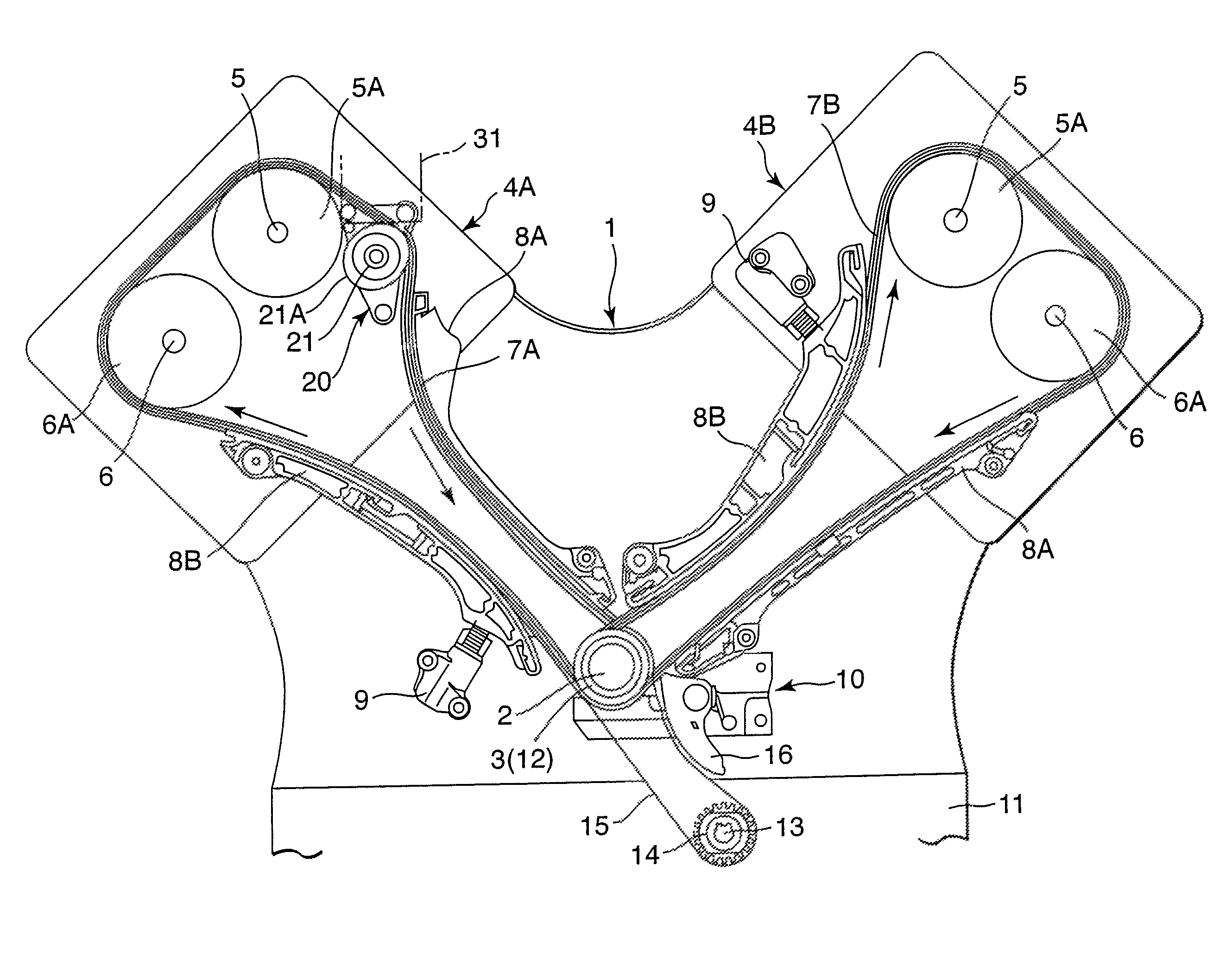
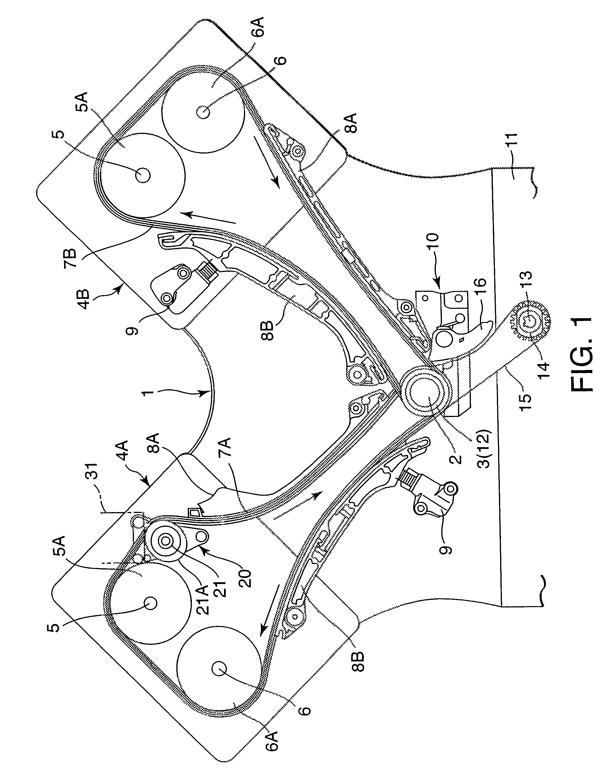
[0021]Referring to FIG. 1 of the drawings, a fuel-pump-driving device 20 operates with a rotational force transferred by a timing chain 7A of a V-shaped internal combustion engine, which serves as an endless torque transmitting member.

[0022]The internal combustion engine comprises a crankshaft 2 projecting outward from a cylinder block 1. A crank sprocket 3 serving as a rotational drive member is fixed to a projecting end of the crankshaft 2. A pair of cylinder heads 4A and 4B are fixed to an upper end of the cylinder block 1. An intake camshaft 5 for opening and closing intake valves and an exhaust camshaft 6 for opening and closing exhaust valves project respectively outward from each of the cylinder heads 4A and 4B. A valve-driving sprocket 5A serving as a rotational driven member is fixed to a projecting end of the intake camshaft 5, and a valve-driving sprocket 6A that also serves as a rotational driven member is fixed to a projecting end of the exhaust camshaft 6.

[0023]The tim...


PUM


Abstract

A fuel-pump-driving device (20) drives a plunger (31) of a fuel pump (30) to perform a reciprocating motion to supply fuel to an internal combustion engine. The fuel-pump-driving device (20) comprises a cam (27) that drives the plunger (31) according to the rotation of a fuel-pump-driving sprocket (26). The fuel-pump-driving sprocket (26) meshes with a chain (7A) which travels between a crank sprocket (3) and a valve-driving sprocket (5A) of the engine. Since the fuel-pump-driving sprocket (26) can be located in a position detached from the valve-driving sprocket (5A), the fuel-pump-driving device (20) has greater freedom of layout and the fuel pump (30) exhibits a better performance than in a case where the plunger (31) is driven by a cam that is fixed directly to the cam shaft (5) of the valve-driving sprocket (5A).

Description

FIELD OF THE INVENTION[0001]This invention relates to a driving device for a fuel pump which supplies fuel to an internal combustion engine.BACKGROUND OF THE INVENTION[0002]JP 2005-036711A, published by the Japan Patent Office in 2005, discloses a fuel pump which supplies fuel to an internal combustion engine.[0003]The internal combustion engine comprises intake valves and exhaust valves as well as a camshaft which rotates in a fixed relation with the rotation of the engine to open and close the intake valves and exhaust valves. A crank sprocket is fixed to the crankshaft and a valve-driving sprocket is fixed to the camshaft. A timing chain is wrapped around the crank sprocket and the valve-driving sprocket to transmit the rotational force of the crankshaft to the camshaft. Valve-driving cams are fixed to the camshaft to open / close the intake valves and the exhaust valves when the camshaft is rotated by the rotational force of the camshaft.[0004]The fuel pump comprises a pressure ch...

Claims


Application Information

Patent Timeline
Patent Type & Authority Patents(United States)
IPC IPC(8): F02M37/06F02M37/04
CPCF01L1/02F01L1/024F02B67/06F02M59/102
Inventor MARUYAMA, NORIYOSHI
Owner NISSAN MOTOR CO LTD
Why Eureka
Try Eureka