Arrangement for telescopic fork leg with parallel damping

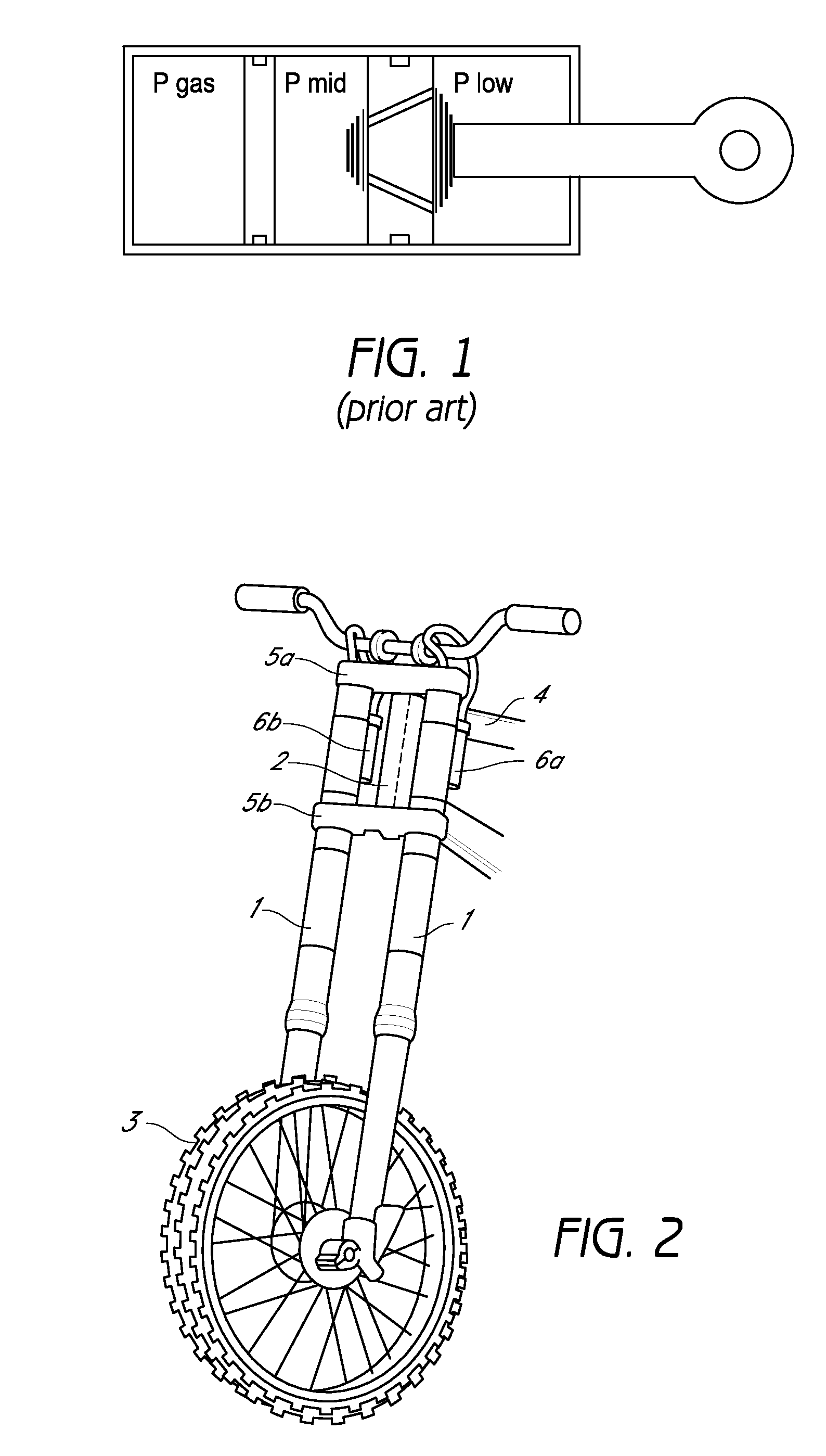
a technology of parallel damping and telescopic forks, which is applied in the direction of vibration dampers, resilient suspensions, vehicle springs, etc., can solve the problems of high flow speed, limited use area of dampers, and low pressure build-up of u.s. pat. no. 6,260,832

Active Publication Date: 2010-08-03
OHLINS
View PDF13 Cites 17 Cited by
  • Summary
  • Abstract
  • Description
  • Claims
  • Application Information

AI Technical Summary

Benefits of technology

[0008]The designs according to EP1505315A2 and EP0322608A2 are adapted for shock absorbers that are not subjected to the same forces and impacts as a front fork. A device is thus required for a front fork that comprises adjustable parallel damping. It is also advantageous if the device is able to be adjusted to suit different front fork dimensions and can be used as a kit for modifying an existing front fork.
[0010]In accordance with certain features, aspects and advantages of some embodiments of the present invention, the damping system components comprise two concentric tubes in the form of a damping tube and an outer tube that is arranged around the damping tube. The tubes together form a portion of a removable insert system in the front fork. The insert system creates a double tube function in which the damping medium can flow in parallel as a result of the duct between the damping tube and the outer tube being used to connect together the two chambers and the common pressurizing location. The pressurizing location is connected to the medium flow passages between the damping cylinder and the outer tube via a head that also comprises valves for adjusting the flow of the medium. This insert system forms a compact unit that is simple to adapt to different front fork dimensions and that can also be used as a kit for providing an existing front fork with parallel damping.

Problems solved by technology

U.S. Pat. No. 6,260,832 does not, however, have the desirable build-up of pressure that is described below.
This system has limitations in that the pressures in the two pressurizing locations must more or less harmonize with each other, as the drop in pressure (ΔP1=Plow−Pmid, ΔP2=Pmid−Pgas) across the two pressurizing pistons should be greater than zero in order not to create cavitation.
Because the drop in pressure across the piston is dependent upon the flow resistance through the piston in combination with the force that acts on the piston, the flow resistance, controlled for example by a shims stack, can only be adjusted within a certain limited range, which thus also results in a limited area of use for the damper.
With serial damping, the oil is forced through both of the valves in series, which results in high flow speeds.
With high flow speeds and high piston speeds, the design of the pistons is limited in order not to obtain an unwanted uncontrolled build-up of pressure due solely to the flow resistance.

Method used


Image

  • Arrangement for telescopic fork leg with parallel damping
  • Arrangement for telescopic fork leg with parallel damping
  • Arrangement for telescopic fork leg with parallel damping

Examples


Embodiment Construction

[0022]FIG. 2 shows a front fork mounted on a vehicle, in this embodiment a motorcycle, of which only the front part is shown. Fork legs (1) are arranged on each side of a steering pillar (2). The lower parts of the fork legs (1) are attached to the wheel (3) and the upper ends are connected to the frame (4) via the top yoke and bottom yoke (5a, 5b). According to this embodiment, each fork leg (1) of the front fork has an external pressure chamber (6a, 6b) that is attached to the respective fork leg (1). Other fixing locations for the pressure chamber are possible, for example in the yoke, in the frame or on the steering pillar.

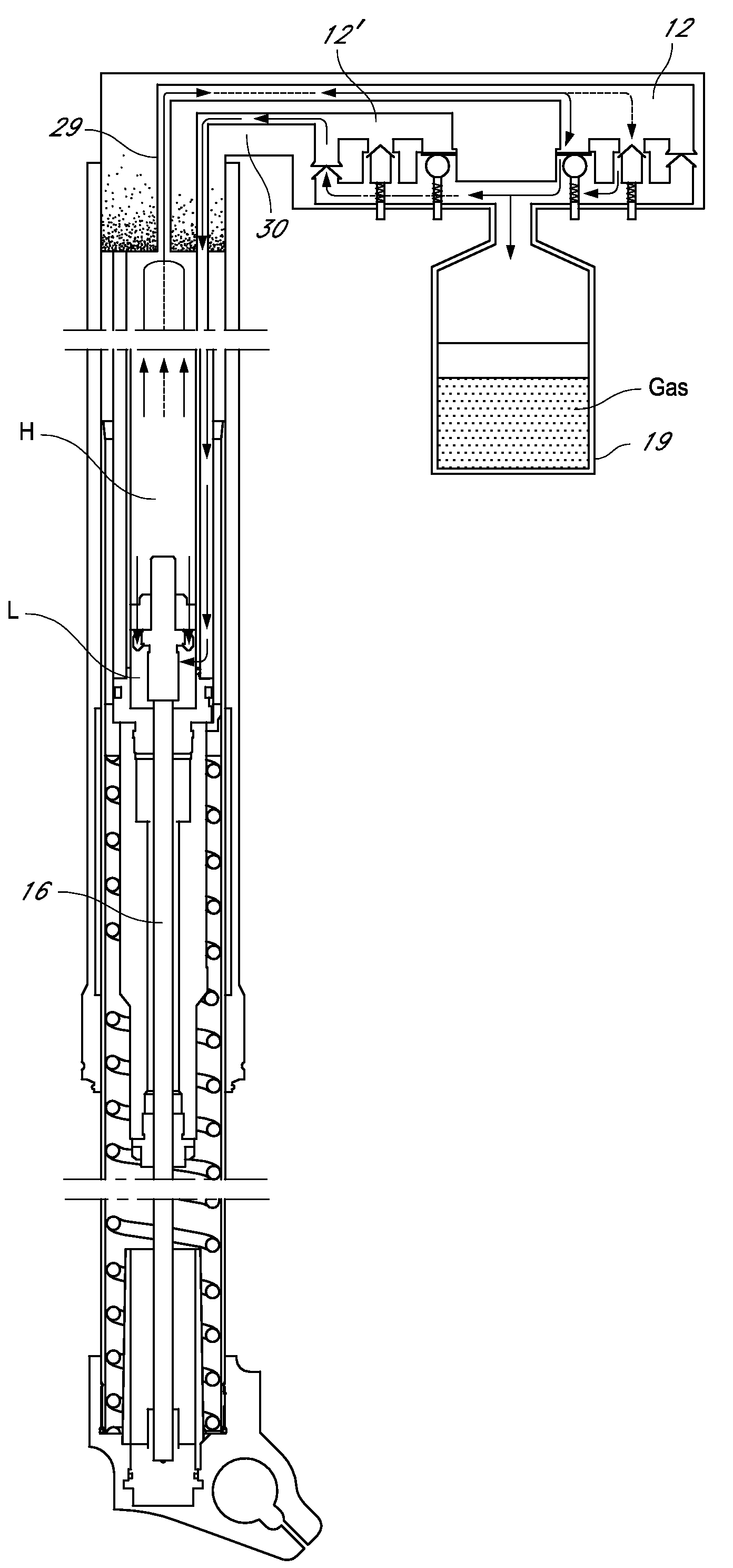
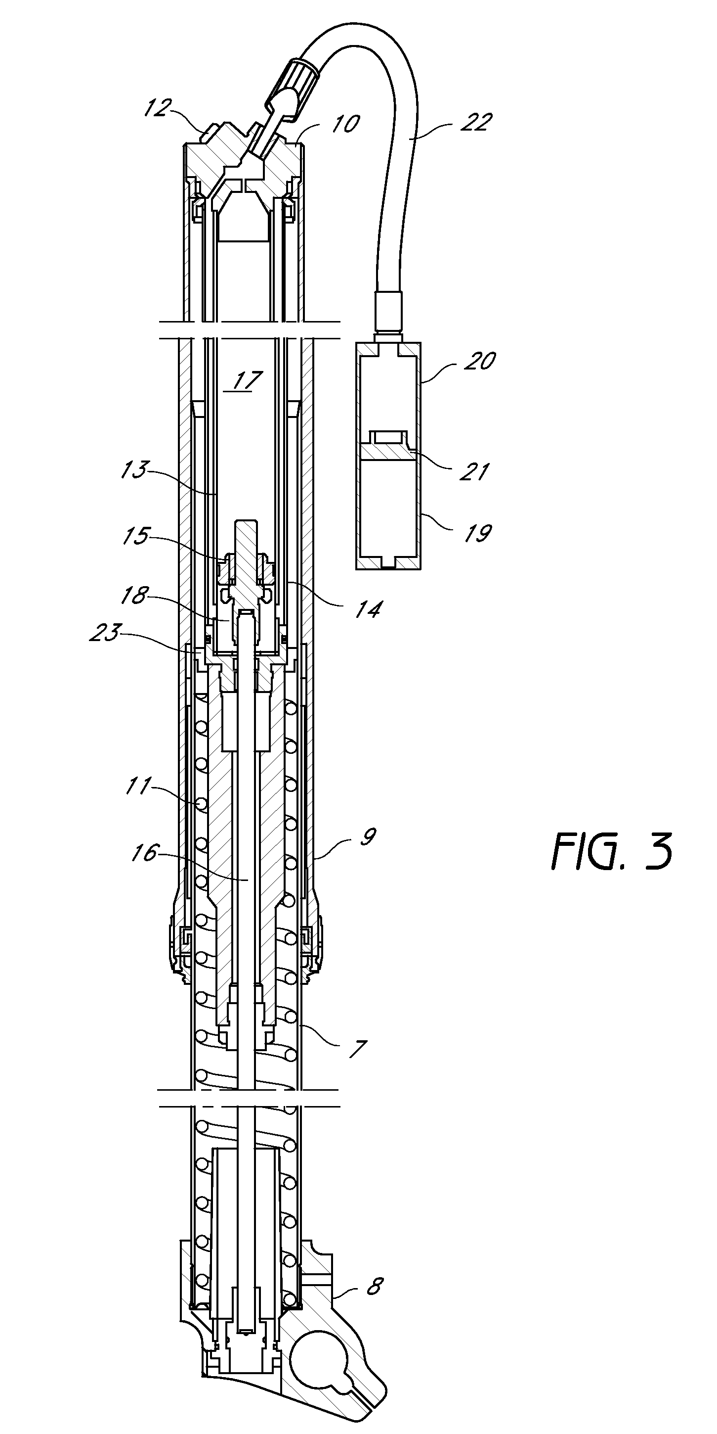
[0023]FIG. 3 shows the front fork in cross section and its construction and function are described below in greater detail. The front fork comprises a lower inner leg (7) arranged on a bottom unit (8) and an upper outer fork leg (9) that terminates in a head (10) that seals the fork. A spring (11) is arranged in the lower inner leg (7) and the damping system i...


PUM


Abstract

A device for telescopic fork legs, preferably for a motorcycle or bicycle. The device is a compact removable unit that comprises parallel medium flow passages that run between upper and lower sides of the piston. This unit that is simple to adapt to different front fork dimensions and to use as a kit for providing an existing front fork with parallel damping. Parallel damping achieves simple adaptation of the damping characteristics to different types of terrain.

Description

CROSS-REFERENCE TO RELATED APPLICATIONS[0001]This application is a U.S. National Phase of International application No. PCT / SE2006 / 001187, filed Oct. 18, 2006, which is based upon Swedish Patent Application No. 0502310-6, filed Oct. 19, 2005, each of which is hereby incorporated by reference in its entirety and priority is claim to each of these applications.BACKGROUND OF THE INVENTION[0002]1. Field of the Invention[0003]The present invention relates to a device for telescopic fork legs, preferably on a motorcycle or bicycle, where the telescopic fork leg comprises outer and inner legs and a damping system with a piston and piston rod arrangement that is arranged within these.[0004]2. Description of the Related Art[0005]A front fork for a motorcycle or a bicycle can be subjected to wheel speeds in the whole range of 0-10 m / s and stroke lengths of up to 300 mm. In order to be able to absorb such high speeds and such large strokes, great demands are made of the front fork. It must be ...

Claims


Application Information

Patent Timeline
Patent Type & Authority Patents(United States)
IPC IPC(8): F16F9/44B62K21/00
CPCB60G15/061B60G17/04B60G17/08F16F9/46B62K25/08F16F9/062F16F9/065B60G2202/154B60G2300/12B60G2500/20B60G2500/11F16F9/512
Inventor SINTORN, TORKEL
Owner OHLINS
Why Eureka
Try Eureka