System for the spraying of spray liquid for aircraft windshield, and cockpit provided with such a spraying system

a spray system and aircraft windshield technology, applied in vehicle maintenance, vehicle cleaning, launching weapons, etc., can solve the problems of clogging the piping system, entail a major loss of time, and long installation process of the purging device, etc., and achieve the effect of simple installation and low cos

Active Publication Date: 2013-06-18
AIRBUS OPERATIONS (SAS)
View PDF7 Cites 4 Cited by
  • Summary
  • Abstract
  • Description
  • Claims
  • Application Information

AI Technical Summary

Benefits of technology

[0014]In one embodiment, it is sought to provide a purging device that is simple to install and costs little. It is also sought to provide a purging device of this kind that is compact.
[0017]The air compressor of the disclosed embodiments can tap air directly at the position where it is situated, thus eliminating the entire length of tubing for conveying air from a particular position where it is tapped up to the nozzles. For, if the air compressor is available in the vicinity of the nozzles and hence of the windshield, the tubing length needed to convey compressed air is reduced. Furthermore, it is possible to install the entire equipment of the purging device of the disclosed embodiments directly in the nose of the aircraft. Thus, the general space requirement of the purging device is reduced. Furthermore, once the purging device has been installed and connected, the test for verifying the efficient operation of said purging device can be done immediately. It is not necessary to supply pressurized air since the compression device makes direct use of the air available in the vicinity.
[0019]The auxiliary or ancillary compression means are additional compression means in the sense that they are added on to the spraying system specifically to compress the gas to be sprayed and are independent of the engines of the aircraft that is provided with said spraying system of the disclosed embodiments. The spray liquid spraying system of the disclosed embodiments forms an independent unit capable of working autonomously, i.e. independently of the aircraft on which it is designed for use. Such a spraying system advantageously forms a compact unit, each of the elements of said system being grouped together in a same zone of the aircraft. Installing the compression means in the vicinity of the windshields reduces the length of the pipes designed to convey the compressed gas up to said windshields. The compression means used in the prior art, on the contrary, are a turbo-jet engine of the aircraft most usually positioned at the level of the wings and therefore at a distance from the windshields, thus necessitating a substantial length of tubing.
[0027]the pressurized-gas supply circuit is provided with at least one backflow check valve capable of preventing the passage of spray liquid in the portion of the pressurized-gas supply circuit positioned upstream from said backflow check valve.
[0031]Advantageously, and in order to reduce the general space requirement of the spraying device according to the disclosed embodiments, and more particularly of the purging device, the compression means can be positioned beneath the floor of the cockpit so that they are in the immediate vicinity of the windshield. Thus, the piping of the pressurized-gas supply circuit has a very small length.
[0032]Furthermore, the pressurized gas air tap can be taken directly beneath the floor of said cockpit. In this case, the fact of tapping air beneath the floor of the cockpit creates a tiny air leak since in flight, below a certain attitude, the air pressure within the aircraft is higher than the air pressure outside the aircraft. Naturally, air can also be tapped outside the cockpit of the aircraft in an unpressurized zone to prevent even a tiny risk of leakage. It is possible to provide for a tightly sealed air tap in the radome, i.e. the nose of the aircraft generally comprising a radar, or on the skin of the aircraft.

Problems solved by technology

The water-repellent liquid used to improve visibility through the windshield 6 has the main drawback of gradually clogging the piping system by the accumulated depositing of silicone on the walls of the piping system and in the nozzles 5.
One of the drawbacks of the prior-art purging device 10 is that it necessitates the use of a tubing 11 that transits from the nose of the aircraft to the central section of said aircraft in which the turbo-jet engines are situated.
Furthermore, the installation of the purging device 10 is a lengthy, complex process.
The phases of the definition, manufacture, installation and testing of the prior-art purging device 10 thus entail a major loss of time.
In this case, the fact of tapping air beneath the floor of the cockpit creates a tiny air leak since in flight, below a certain attitude, the air pressure within the aircraft is higher than the air pressure outside the aircraft.

Method used


Image

  • System for the spraying of spray liquid for aircraft windshield, and cockpit provided with such a spraying system
  • System for the spraying of spray liquid for aircraft windshield, and cockpit provided with such a spraying system
  • System for the spraying of spray liquid for aircraft windshield, and cockpit provided with such a spraying system

Examples


Embodiment Construction

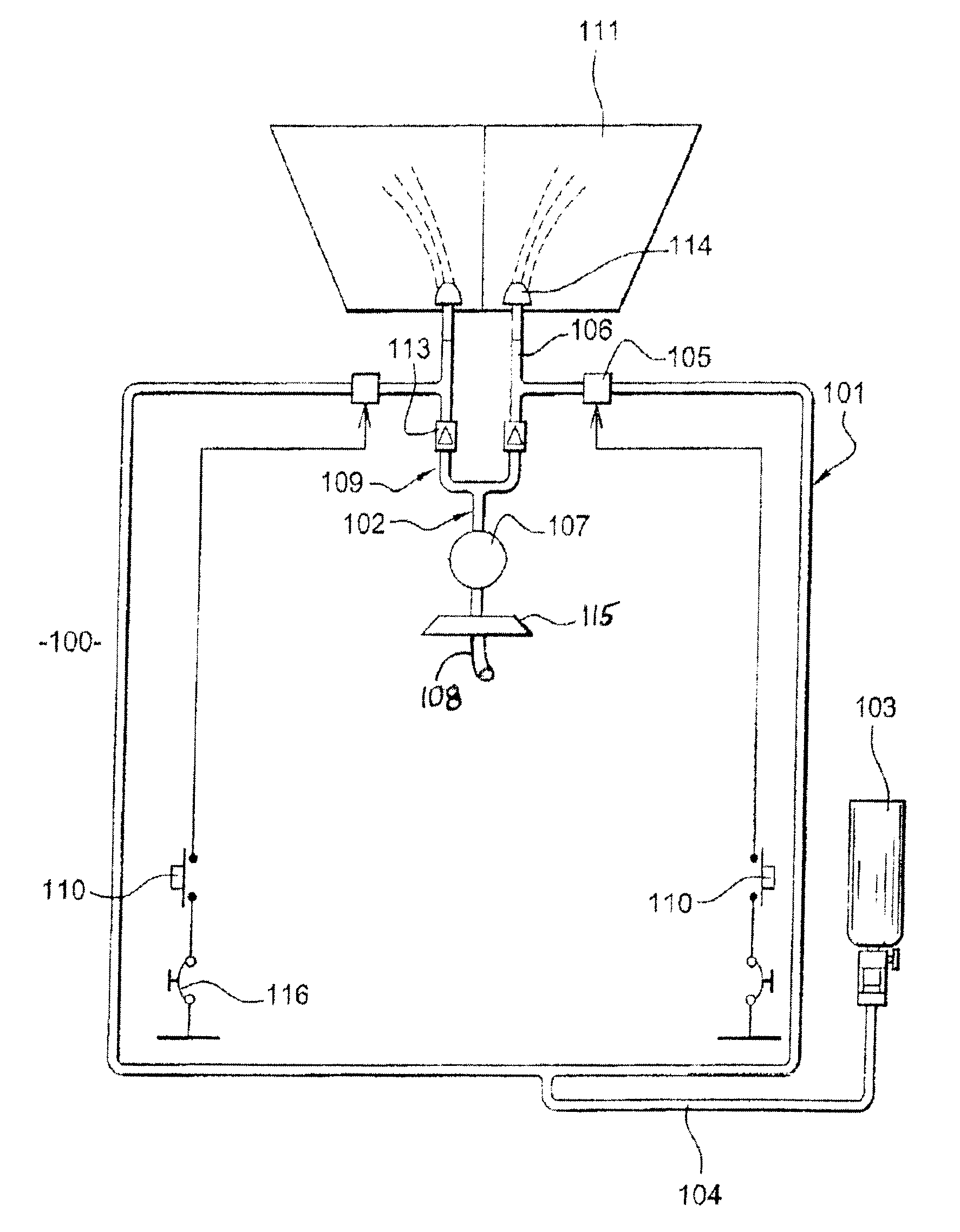
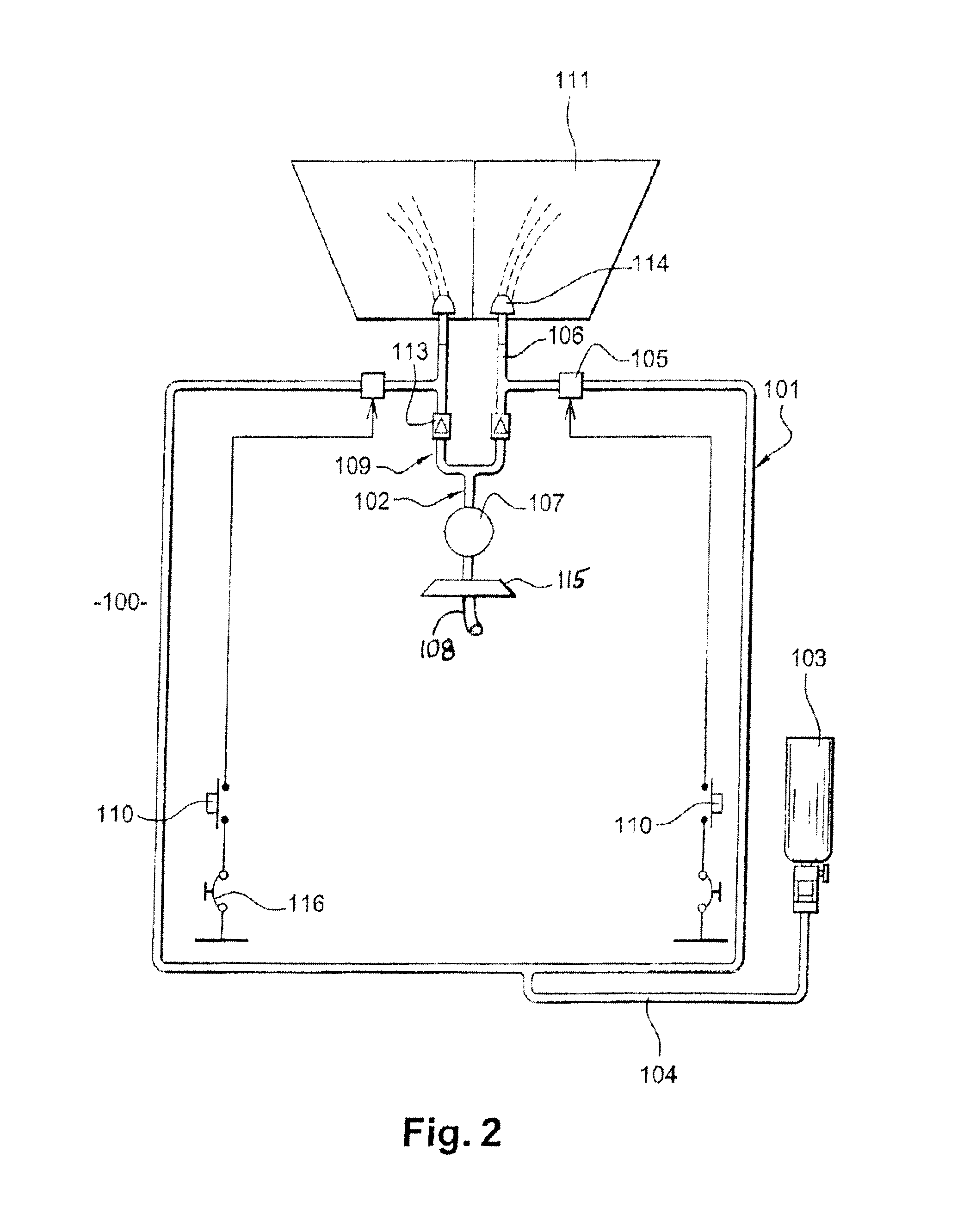
[0038]FIG. 2 shows a system 100 for the spraying of spray liquid for windshields 111 according to the disclosed embodiments. The spraying system 100 comprises a spray-liquid supply circuit 101 and a pressurized-gas supply circuit 102.

[0039]The spray-liquid supply circuit 101 has a tank 103 containing pressurized spray liquid. A first piping portion 104 is used to convey the pressurized spray liquid from the tank 103 to valves 105 blocking the pressurized spray liquid in this first piping portion 104 when the spraying system 100 is not actuated. The valves 105 of the spray-liquid supply circuit 101, when actuated, permit the passage of the spray liquid into the second piping portion 106 of the spray-liquid supply circuit 101, this second piping portion 106 enabling the pressurized spray liquid to be conveyed from the valve 105 up to the nozzles 114.

[0040]The pressurized-gas supply circuit 102 has an auxiliary compressor 107 capable of constantly compressing air tapped at the level of...


PUM


Abstract

A system for spraying liquid (100) for a windshield (111) of an aircraft including a spray-liquid supply circuit (101), a pressurized-gas supply circuit (102) designed to purge the spray-liquid supply circuit, and at least one nozzle (114) disposed downstream from the circuits and designed to spray the spray liquid and pressurized gas on a windshield, characterized in that the system includes an auxiliary means of compression (107) ready to compress gas designed to circulate in the pressurized-gas supply circuit, the auxiliary means of compression being positioned near the nozzle. Also, an aircraft cockpit provided with at least such a spray system.

Description

BACKGROUND[0001]1. Field[0002]The disclosed embodiments relate to a system for the spraying of spray liquid for aircraft windshields. More specifically, the disclosed embodiments relate to a purging device used to clean a spray system of this kind and eliminate all traces of spray liquid from the piping system after the spraying of such liquid. The disclosed embodiments also relate to an aircraft cockpit comprising at least one such system for the spraying of spray liquid.[0003]When an aircraft is in flight, and in the event of heavy rain, there are known ways of improving visibility inside the aircraft cockpit by spraying a hydrophobic liquid or water-repellent liquid, most usually consisting of silicone or solvent, on the exterior of the windshield of said cockpit. The water-repellent liquid is preferably used when the aircraft is in flight because, when the aircraft is on the ground, this water-repellent liquid cannot be sprayed fast enough on the windshield.[0004]2. Description ...

Claims


Application Information

Patent Timeline
Patent Type & Authority Patents(United States)
IPC IPC(8): B05B1/10
CPCB60S1/481B64C1/1476
Inventor LE LOUARN, AMELIECHENE, GILLES
Owner AIRBUS OPERATIONS (SAS)
Why Eureka
Try Eureka