Flow generator for use in connection with a utility conduit

a technology of flow generator and utility conduit, which is applied in the direction of electric generator control, control system, climate sustainability, etc., can solve the problems of limited natural resources such as oil and coal, which have been energy sources, and may not be able to meet the energy needs of the growing population of the world, and achieve the effect of safe and efficient sources of energy

Inactive Publication Date: 2010-08-03
BALZANO ALFIERO
View PDF25 Cites 48 Cited by
  • Summary
  • Abstract
  • Description
  • Claims
  • Application Information

AI Technical Summary

Benefits of technology

[0013]It is contemplated that the power generation and distribution system may provide a safe and efficient source of energy without consuming valuable natural resources. The power generation and distribution system may also provide energy without producing emissions which may harm the environment. Rather, the system captures the energy of a fluid passing through a utility conduit and converts that energy into an energy form that may be used by homes and businesses.

Problems solved by technology

There are concerns that traditional energy sources may not be able to support the energy needs of the world's growing population.
Furthermore, limited natural resources such as oil and coal, which have been sources of energy for many years, may be depleted before too long.
The diminishing supply of these natural resources also makes energy more expensive, as evidenced by the rising cost of oil.
In addition, traditional energy sources tend to be undesirable because of their negative impact on the environment.
For instance, the burning of coal produces harmful emissions which may cause damage the ozone layer.
The harmful emissions may also create human health problems, such as respiratory and allergy conditions.
As such, given that traditional energy sources may be limited and that they may have negative environmental impact, the art recognizes that alternate energy sources may be needed to replenish or supplement traditional energy sources.
Other areas which are deprived from abundant sun and wind may not be suited for solar and wind generated power alternatives.
As such, these areas may be forced to rely on undesirable traditional energy generation methods.

Method used


Image

  • Flow generator for use in connection with a utility conduit
  • Flow generator for use in connection with a utility conduit
  • Flow generator for use in connection with a utility conduit

Examples


Embodiment Construction

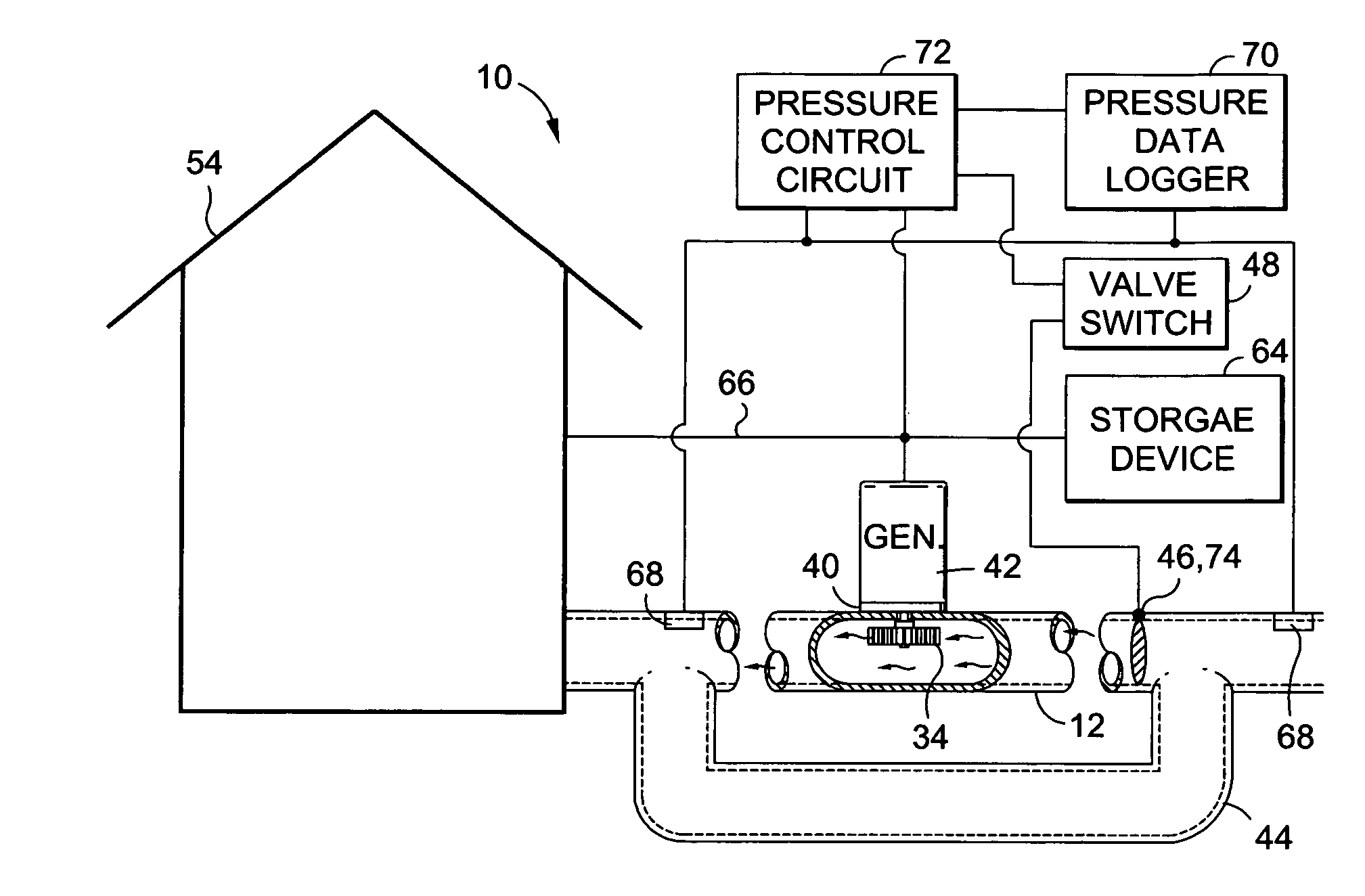
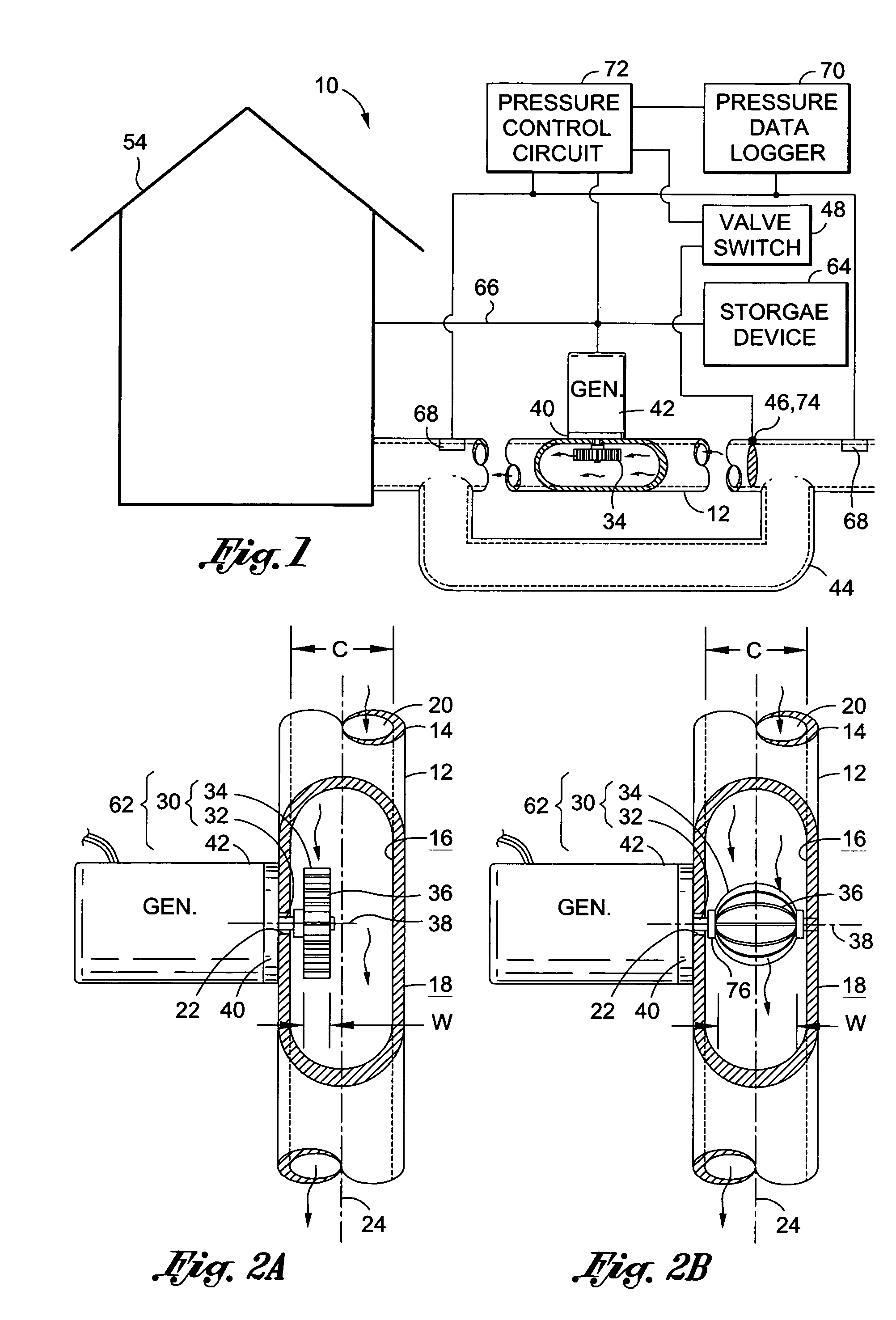
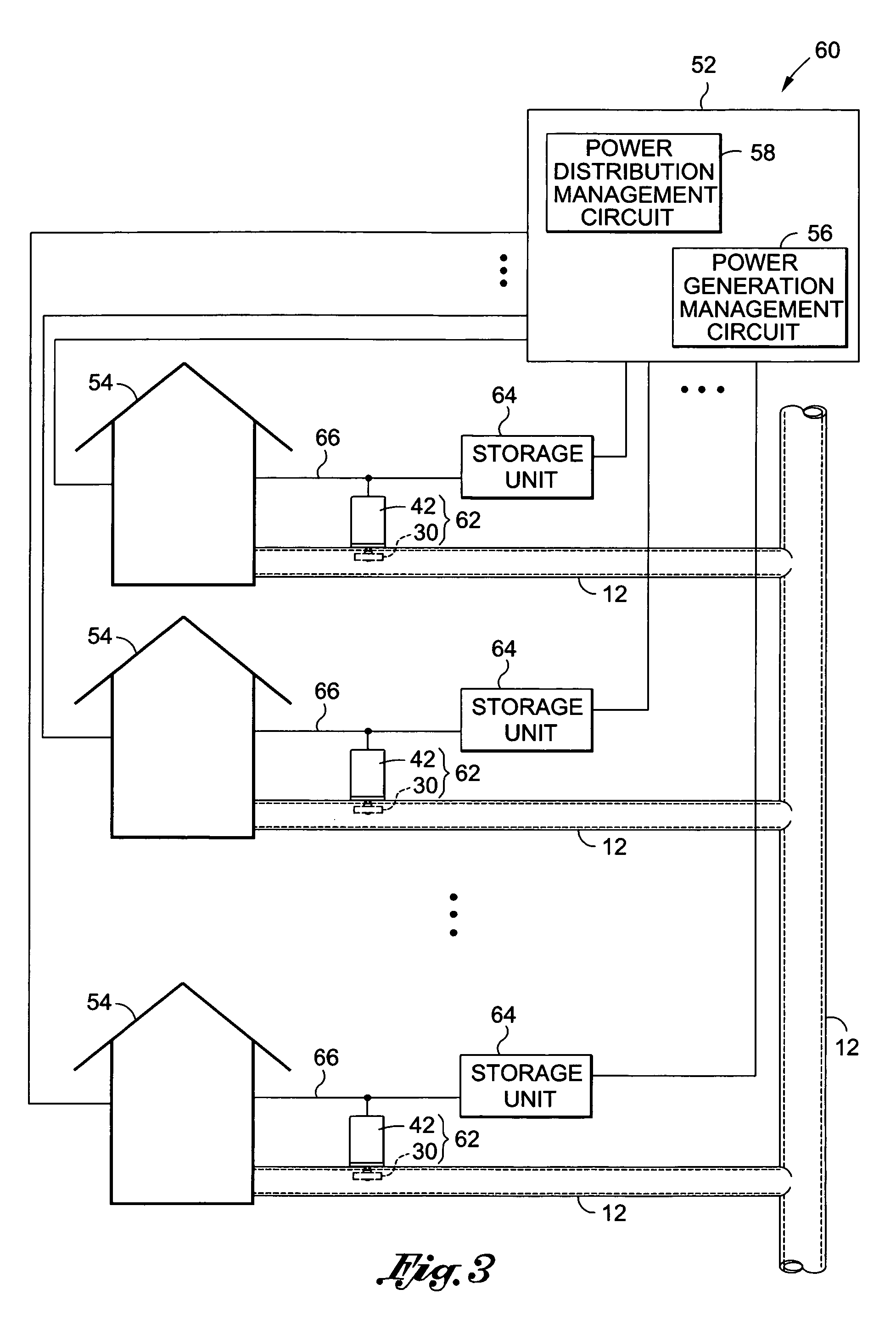
[0024]Referring now to the drawings wherein the showings are for purposes of illustrating a preferred embodiment of the present invention only, and not for purposes of limiting the same, there is shown a power generation and distribution system 10 constructed in accordance with an embodiment of the present invention. It is contemplated that various aspects of the present invention are directed toward an energy solution that may be used in connection with a utility conduit to provide an inexpensive alternative or supplemental energy source. In addition, other aspects of the present invention are directed toward mitigating pressure loss within the utility conduit 12. Furthermore, as set forth below, the power generation and distribution system 10 may provide energy without consuming valuable natural resources or producing environmentally harmful emissions.

[0025]Referring now specifically to FIG. 1, there is shown a particular embodiment of the power generation and distribution system ...


PUM


Abstract

There is provided a power generation and distribution system for use in combination with a utility conduit having fluid passing therethrough. The power generation and distribution system includes a rotation element disposable within the utility conduit. The rotation element rotates in response to fluid passing within the utility conduit. A power generator is in mechanical communication with the rotation element, and generates power in response to rotation of the rotation element. This system also includes a power distributor in electrical communication with the power generator and electrically connectable to a power outlet to distribute power thereto.

Description

CROSS-REFERENCE TO RELATED APPLICATIONS[0001]Not ApplicableSTATEMENT RE: FEDERALLY SPONSORED RESEARCH / DEVELOPMENT[0002]Not ApplicableBACKGROUND[0003]1. Field of the Invention[0004]The present invention relates generally to an energy production system and more particularly, to a power generation and distribution system for use in combination with a utility conduit having fluid passing therethrough.[0005]2. Description of the Related Art[0006]One of the more important issues currently affecting the global community is energy generation and management. There are concerns that traditional energy sources may not be able to support the energy needs of the world's growing population. For instance, rolling blackouts are already common occurrences in heavily populated areas. Furthermore, limited natural resources such as oil and coal, which have been sources of energy for many years, may be depleted before too long. The diminishing supply of these natural resources also makes energy more exp...

Claims


Application Information

Patent Timeline
Patent Type & Authority Patents(United States)
IPC IPC(8): F03B13/00
CPCF03B13/00F05B2220/60F05B2220/604Y02B10/50
Inventor BALZANO, ALFIERO
Owner BALZANO ALFIERO
Why Eureka
Try Eureka