Unlock instant, AI-driven research and patent intelligence for your innovation.

Focal control adjusting method and optical disk apparatus

a technology of optical disk and adjustment method, which is applied in the direction of digital signal error detection/correction, instruments, recording signal processing, etc., can solve the problems of deteriorating focal control performance, disturbance is easily generated in the focal error signal, and deterioration of focal control performance, so as to achieve high precision and achieve stably the effect of focal control performan

Inactive Publication Date: 2010-08-03
SOCIONEXT INC
View PDF12 Cites 0 Cited by
  • Summary
  • Abstract
  • Description
  • Claims
  • Application Information

AI Technical Summary

Benefits of technology

The present invention provides a focal control adjusting method for an optical disk apparatus that can control a positional shift between a recording surface of a recording medium and a light beam spot when the light beam moves in a track on the recording medium. The method uses a focal error signal that is detected by a position detection system and a focal control gain that is determined based on the focal error signal. The method dynamically adjusts the coefficient used for the multiplication of the position detection signals based on the amplitude change of the focal error signal, so that the disturbance component superposed on the focal error signal is controlled and the focal control operation can be stably realized even if the mounting precision of the optical components and transfer mechanism, and depths of the disk grooves vary. This technology can improve the performance of the optical disk apparatus and any instrument in which it is installed.

Problems solved by technology

In the astigmatic focal error method, a disturbance is easily generated in the focal error signal when a condensed spot of the light beam irradiated on the recording medium (hereinafter, refereed to as light beam spot) traverses a track on the recording medium.
However, in the case of generating the focal error signal based on the return light (reflected light), the disturbance is easily generated in the focal error signal because an intensity distribution pattern of the reflected light periodically changes under the influence of the diffraction by the guiding grooves in the disk 1, and leak of the push-pull signal component thereby generated.
Accordingly, the disturbance component unfavorably remains in the focal error signal actually used for the focal control, which may deteriorate a focal control performance.
As another disadvantage, there is no choice except to variously set a coefficient multiplied to the position detection signal in the canceling processing conducted in the conventional example described above, which also generates the situation where the disturbance component unfavorably remains in the focal error signal actually used for the focal control.
Accordingly, there is a case that the focal control performance may be deteriorated.
In the conventional control method, drive currents applied to the actuators 2-9-1 and 2-9-2 as the focal control signal are excessively large, which disadvantageously increases loads to the actuators 2-9-1 and 2-9-2.

Method used


Image

  • Focal control adjusting method and optical disk apparatus
  • Focal control adjusting method and optical disk apparatus
  • Focal control adjusting method and optical disk apparatus

Examples


embodiment 1

Preferred Embodiment 1

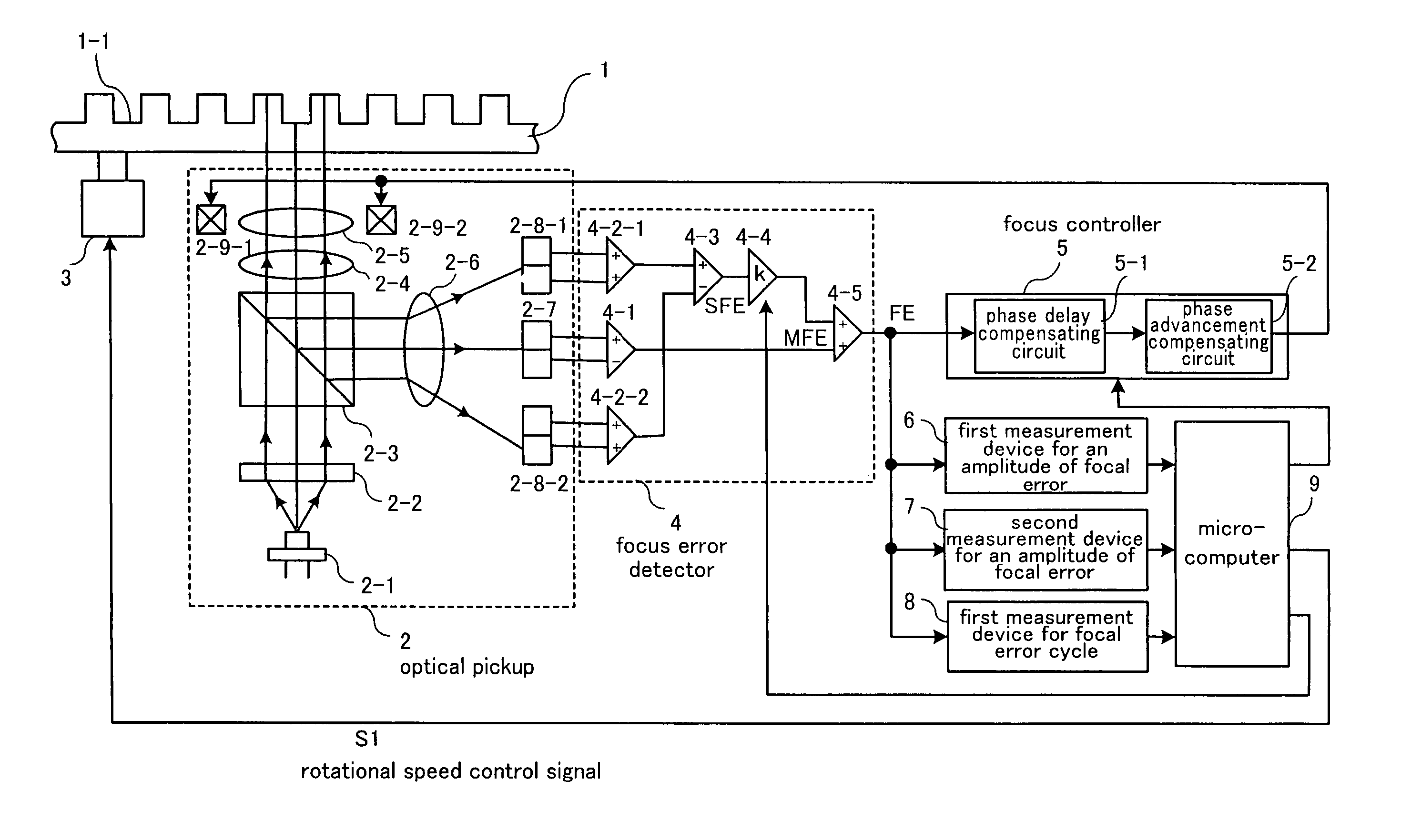
[0053]FIG. 1 is a block diagram illustrating an example of structure with respect to an optical disk apparatus in which a focal control adjusting method according to a preferred embodiment 1 of the present invention is conducted. In the optical disk apparatus, a DVD-RAM disk, which is an example of a recording medium (hereinafter, referred to as disk) 1, is installed. A motor 3 rotates the disk 1. The motor 3 is controlled in accordance with a rotational speed control signal S1 outputted from a microcomputer 9. A light source 2-1 is an element for emitting a light beam of, for example, 650 nm. The light beam emitted from the light source 2-1 enters a diffraction grating 2-2 so as to be divided therein into at least three light beams, which are a main light beam transmitting just through the diffraction grating 2-2 (zero-order light) and two sub light beams progressing separately from the main light beam at a predetermined diffraction angle (positive first-order...

embodiment 2

Preferred Embodiment 2

[0102]FIG. 11 is a block diagram illustrating an example of an optical disk apparatus in which a focal control adjusting method according to a preferred embodiment 2 of the present invention is installed. The reference numerals shown in FIG. 11 corresponding to those shown in FIG. 1 denote the same components, which are, therefore, not described in detail again. In FIG. 11, a reference numeral 11 denotes a transfer mechanism for moving the optical pickup 2 to an arbitrary position in direction to traverse the track 1-1 of the disk 1. The transfer mechanism 11 can move the object lens 2-5, which is a component of the optical pickup 2, to the arbitrary position in direction to traverse the track 1-1. Therefore, the transfer mechanism 11 can also move the light beam spot to an arbitrary position in direction to traverse the track 1-1. The transfer mechanism 11 is position-controlled based on a transfer mechanism control signal S2 supplied from the microcomputer 9....


PUM

PropertyMeasurementUnit
wavelengthaaaaaaaaaa
rotational speedaaaaaaaaaa
timeaaaaaaaaaa

Abstract

A focal control adjusting method according to the present invention comprises a first step for detecting a focal error signal obtained through condensing and irradiating a light beam on a rotating recording medium, and a second step for setting a focal control gain for controlling a positional shift between a recording surface of the recording medium and the light beam based on the focal error signal detected in the first step, wherein a result obtained by multiplying the position detection signal (sub light beams) by a preset coefficient is added to the position detection signal (main light beam), and a result of the addition is detected as the focal error signal in the first step, and the coefficient is set in accordance with the focal error signal in the first step.

Description

BACKGROUND OF THE INVENTION[0001]1. Field of the Invention[0002]The present invention relates to an optical disk apparatus for reproducing or recording information to a recording medium such as DVD (Digital Versatile Disc) and a method to adjust focal control adapted in the apparatus.[0003]2. Description of the Related Art[0004]It was already known that there are a knife-edge method (Foucault method), a spot size detecting method, an astigmatic focal error method and the like as a conventional method to detect a focal error signal which represent a positional shift between a light beam of the optical disk apparatus and a recording surface of a recording medium. The astigmatic focal error method is the most popular[0005]one in standpoints of its simplified optical system and easiness in, adjustment and the like. In the astigmatic focal error method, a disturbance is easily generated in the focal error signal when a condensed spot of the light beam irradiated on the recording medium (...

Claims


Application Information

Patent Timeline
Patent Type & Authority Patents(United States)
IPC IPC(8): G11B7/00G11B20/18
CPCG11B7/094G11B7/0941G11B7/0945G11B7/09
Inventor KUWAHARA, MASAYA
Owner SOCIONEXT INC