Unlock instant, AI-driven research and patent intelligence for your innovation.

Laser light source device, illumination apparatus, monitor, and projector

a technology of laser light source and illumination device, which is applied in the direction of instruments, semiconductor lasers, optical elements, etc., can solve the problems of insufficient improvement of conversion efficiency of shg elements, inability to achieve highly efficient wavelength conversion, and difficulty in effectively securing the inside of shg elements as optical paths, etc., to achieve the effect of improving conversion efficiency and high power

Inactive Publication Date: 2010-08-03
SEIKO EPSON CORP
View PDF30 Cites 4 Cited by
  • Summary
  • Abstract
  • Description
  • Claims
  • Application Information

AI Technical Summary

Benefits of technology

[0009]An advantage of some aspects of the invention is to improve conversion efficiency in an SHG element and make it possible to generate a laser beam with high power.

Problems solved by technology

However, in the technique in the past, although it is possible to improve characteristics of the SHG element, sufficient improvement of the conversion efficiency cannot be expected in the SHG element because of reasons (A) and (B) below.
Since conversion energy of an optical wavelength conversion element substantially depends on the light beam density of the incident light, when the light beam density of the incident light falls, highly efficient wavelength conversion cannot be performed.
This makes it difficult to effectively secure the inside of the SHG element as an optical path.
Therefore, highly efficient wavelength conversion cannot be performed.

Method used


Image

  • Laser light source device, illumination apparatus, monitor, and projector
  • Laser light source device, illumination apparatus, monitor, and projector
  • Laser light source device, illumination apparatus, monitor, and projector

Examples


first embodiment

1. First Embodiment

[0038]A. Structure of an Entire Apparatus

[0039]FIG. 1 is a schematic diagram of an illumination apparatus 10 according to a first embodiment of the invention. As shown in the figure, the illumination apparatus 10 includes a laser light source device 12 equivalent to a “laser light source device” of the invention and a diffusing element 14 that diffuses a laser beam emitted from the laser light source device 12.

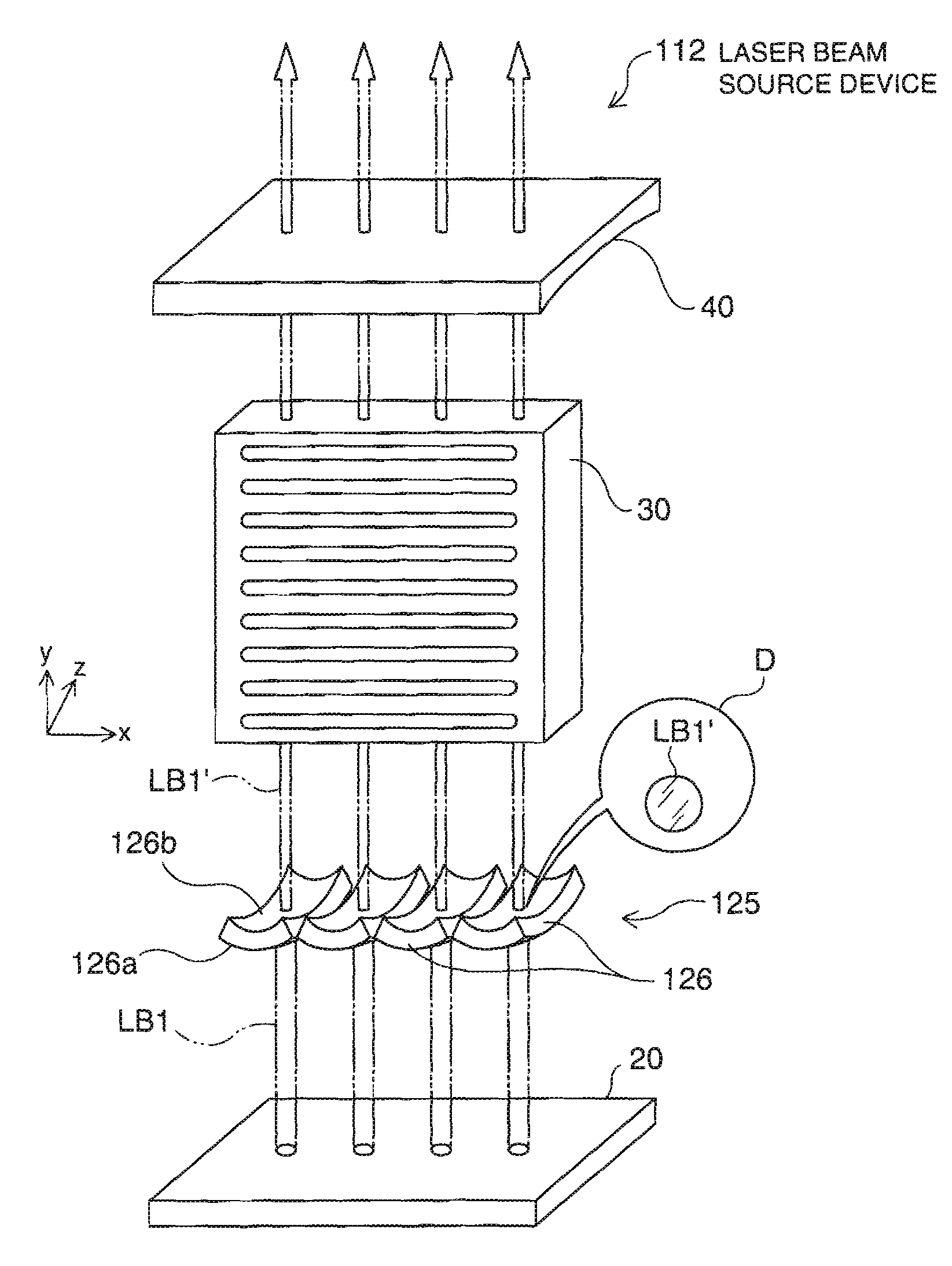
[0040]The laser light source device 12 includes a laser cell 20C incorporating a semiconductor laser array 20, a cylindrical lens 25 of a meniscus shape, a jacket 30C incorporating an optical wavelength conversion element 30, and a reflection mirror 40 functioning as an external optical resonator. The jacket 30C includes a Peltier element for temperature control together with a thermistor to make it possible to highly accurately control the temperature of the optical wavelength conversion element 30. Other heat generating means can be used instead of the Pel...

second embodiment

2. Second Embodiment

[0077]A second embodiment of the invention is explained below. FIG. 9 is a schematic diagram of a monitor 400 according to a second embodiment of the invention. The monitor 400 includes an apparatus main body 410 and an optical transmission unit 420. The apparatus main body 410 includes the laser light source device 12 according to the first embodiment. The laser light source device 12 includes, as explained in the first embodiment, the semiconductor laser array 20, the cylindrical lens 25, the optical wavelength conversion element 30, and the reflection mirror 40.

[0078]The optical transmission unit 420 includes two light guides 421 and 422 on a light transmitting side and a light receiving side. Each of the light guides 421 and 422 is obtained by binding a large number of optical fibers and can transmit a laser beam to a far distance. The laser light source device 12 is disposed on an incidence side of the light guide 421 on the light transmitting side and a dif...

third embodiment

3. Third Embodiment

[0082]A third embodiment of the invention is explained below. FIG. 10 is a schematic diagram of a projector 500 according to a third embodiment of the invention. In the figure, a housing constituting the projector 500 is omitted for simplification of illustration. The projector 500 includes a red laser light source device 501R that emits red light, a green laser light source device 501G that emits green light, and a blue laser light source device 501B that emits blue light.

[0083]The red laser light source device 501R is a general semiconductor laser array that emits a red laser beam LBb. The green laser light source device 501G has a structure identical with that of the laser light source device 12 according to the first embodiment and includes the semiconductor laser array 20, the cylindrical lens 25, the optical wavelength conversion element 30, and the reflection mirror 40. The optical wavelength conversion element 30 performs wavelength conversion to emit a la...


PUM


Abstract

A laser light source device includes a laser light source that emits a laser beam as a fundamental wave and an optical wavelength conversion element that converts the fundamental wave into a second harmonic. An optical lens system including a first surface having positive power and a second surface having negative power is arranged between the laser light source and the optical wavelength conversion element. The first surface and the second surface are arranged in order from the laser light source side.

Description

BACKGROUND[0001]1. Technical Field[0002]The present invention relates to a laser light source device including a laser light source that emits a laser beam and an illumination apparatus, a monitor, and a projector including the laser light source device.[0003]2. Related Art[0004]A second harmonic generation (SHG) technique for generating light having a wavelength half that of incident light is well known as a technique for wavelength conversion. It is possible to obtain a laser beam having a wavelength in a visible region using an easily available semiconductor laser, which oscillates in a far infrared region, by combining this SHG technique with a semiconductor laser technique.[0005]An example of the technique obtained by combining the SHG technique with the semiconductor laser technique is disclosed in JP-A-5-297428. According to the technique, a laser beam emitted from a semiconductor laser is made incident on an SHG element by a lens and converted into a second harmonic. In JP-A...

Claims


Application Information

Patent Timeline
Patent Type & Authority Patents(United States)
IPC IPC(8): H01S3/10
CPCH01S5/4062G02F1/37H01S3/109H01S5/14H01S5/4012H01S5/423
Inventor KAMIJIMA, SHUNJI
Owner SEIKO EPSON CORP